ISO 9001 Certified

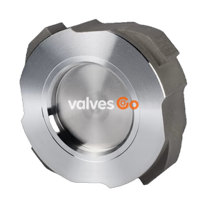
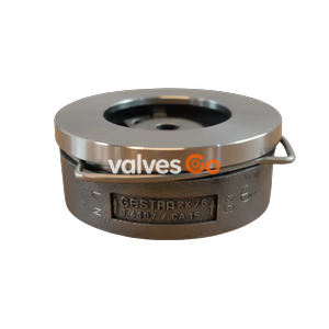
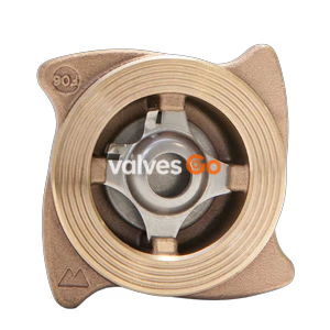
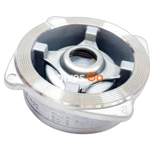
Armstrong CVW40 series wafer lift check valves prevent backflow in hot water, condensate, and oil systems. Features ASTM A351 CF8 stainless steel construction and a cam design for easy centering.
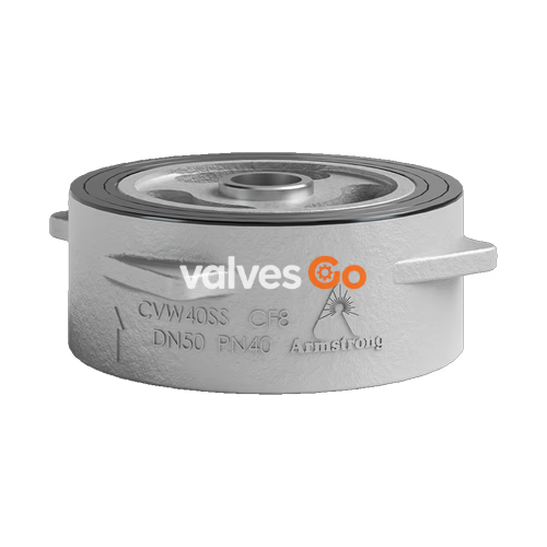
Armstrong CVW40 series wafer lift check valves are designed to effectively prevent the backflow of media in pipelines. They are suitable for non-corrosive fluids such as hot water, condensate, and oil. Compared to traditional swing or lift check valves, the CVW40 series is compact, lightweight, and easy to install. The stainless steel body ensures a long service life and high reliability.
Installation Centering
The "cam" design on the valve body makes it easy to install. By rotating the valve body so that the "cam" contacts the flange connection bolts, you can ensure the valve is perfectly centered in the pipeline.
The wafer lift check valve is an automatic valve that opens by the pressure of the medium. When the medium flow stops, the valve is closed by the force of the spring before reverse flow can occur.
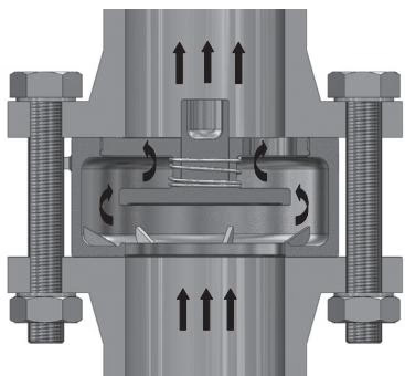 Open
Open
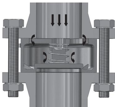 Closed
| Component | Material |
|---|---|
| Body | Stainless Steel ASTM A351 CF8 |
| Disc | Stainless Steel ASTM A351 CF8 |
| Cover | Stainless Steel ASTM A351 CF8 |
| Spring | 304 Stainless Steel |
Application Limit
The check valve is not suitable for applications with severe pulsation, such as near a compressor.
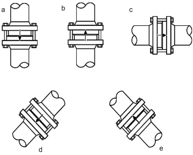
During operation, the system pressure must not be less than the minimum opening pressure (kPa, 1 kPa = 101.93 mm H2O).
| Flow Direction | DN15 | DN20 | DN25 | DN32 | DN40 | DN50 | DN65 | DN80 | DN100 |
|---|---|---|---|---|---|---|---|---|---|
| Up | 8.26 | 6.16 | 4.01 | 5.19 | 4.05 | 2.19 | 3.65 | 2.25 | 2.23 |
| Horizontal | 6.85 | 4.98 | 3.02 | 4.25 | 3.02 | 1.50 | 2.80 | 1.43 | 1.28 |
| Down | 5.44 | 3.80 | 2.01 | 3.31 | 1.99 | 0.83 | 1.91 | 0.61 | 0.32 |
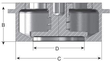
| Nominal Diameter | A (mm) | B (mm) | C (mm) | D (mm) | Weight (kg) |
|---|---|---|---|---|---|
| DN15 | 61 | 30 | 42 | 15 | 0.2 |
| DN20 | 78 | 30 | 52 | 20 | 0.33 |
| DN25 | 78 | 30 | 66 | 25 | 0.44 |
| DN32 | 91 | 35 | 76 | 32 | 0.7 |
| DN40 | 103 | 35 | 86 | 40 | 0.76 |
| DN50 | 119 | 40 | 99 | 50 | 1.0 |
| DN65 | 154 | 50 | 125 | 65 | 2.1 |
| DN80 | 158 | 60 | 134 | 80 | 2.4 |
| DN100 | 189 | 75 | 160 | 100 | 4.3 |
Valves should be stored in a dry, ventilated room. For long-term storage, check regularly, paying special attention to the cleanliness of the sealing surfaces to prevent damage.
Safety Warning
Before maintenance, confirm that the system pressure has dropped to zero (gauge pressure) and wait until the product temperature drops to room temperature. Ensure the medium in the pipeline has been blocked to prevent injury from leakage.
| Potential Fault | Cause | Solution |
|---|---|---|
| Sealing surface leakage | Dirt attached to the sealing surface | Clean the dirt |
| Sealing surface damaged | Grind or replace | |
| Not closing tightly | Dirt stuck in spring clearance causing failure | Clean the dirt |
| Spring fatigue or damage | Replace the spring |
Explore similar products in our catalog