
Skip to content
14/16 Ga Galvanized Steel5/8" Standard ODCentifeed & Standard

Armstrong Duralite™ 板翅蒸汽盘管 Duralite™ Plate Fin Coils

Armstrong Duralite™ Plate Fin Coils for HVAC and light industrial applications. Available in Centifeed, Standard, and Return Bend designs with 5/8" or 1" OD tubes.
Armstrong Duralite™ 板翅蒸汽盘管 Duralite™ Plate Fin Coils

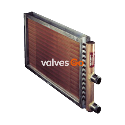
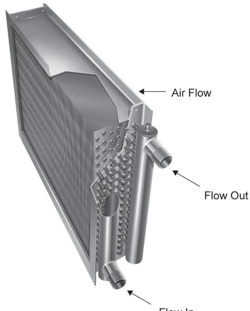
Armstrong Duralite™ Plate Fin Coils meet the diverse needs of the HVAC and light industrial markets. Building on a tradition of quality and dependability, these heavy-duty industrial coils have been serving the process needs of heavy industry for nearly half a century. The coils are available in Centifeed (Steam Distributing Tube Type), Standard (Opposite End Connections), and Two-Row Return Bend Construction.

Construction and Materials

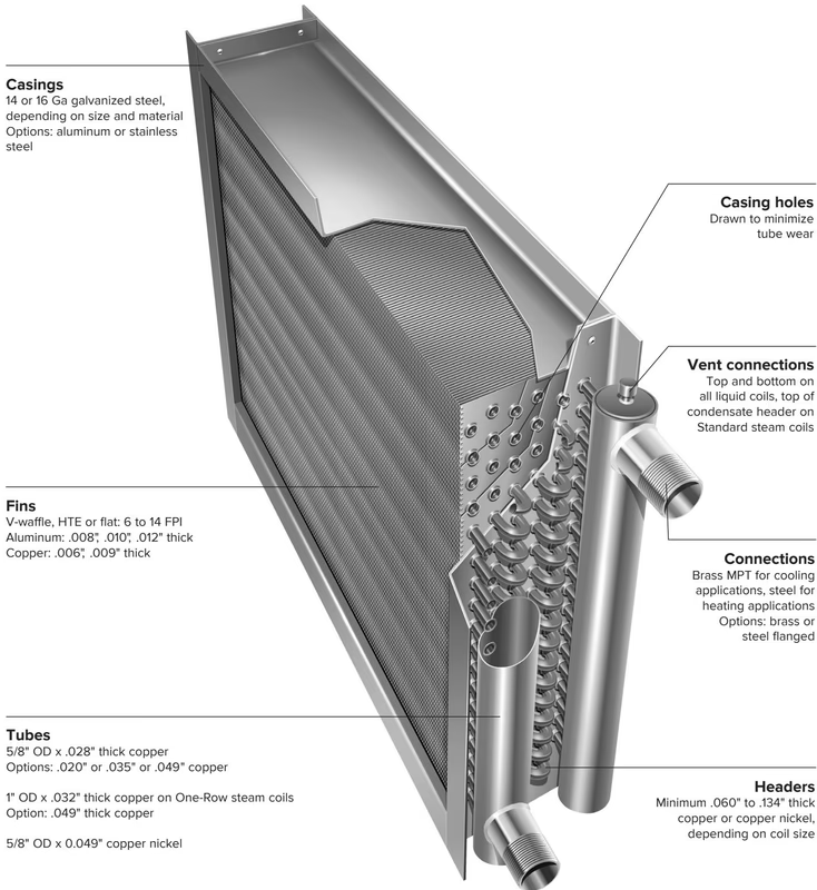
Casings

14 or 16 Ga galvanized steel, depending on size and material. Options include aluminum or stainless steel.
Armstrong Duralite™ 板翅蒸汽盘管 Armstrong Duralite™ Plate Fin Coils casings and fins

Fins

  • Types: V-waffle, HTE or flat: 6 to 14 FPI
  • Aluminum: .008", .010", .012" thick
  • Copper: .006", .009" thick

Tubes

  • 5/8" OD x .028" thick copper (Options: .020" or .035" or .049" copper)
  • 1" OD x .032" thick copper on One-Row steam coils (Option: .049" thick copper)
  • 5/8" OD x 0.049" copper nickel

Connections

  • Headers: Minimum .060" to .134" thick copper or copper nickel, depending on coil size.
  • Vent connections: Top and bottom on all liquid coils, top of condensate header on Standard steam coils.

Connection Types:

  • H = Liquid Heating Coil
  • S = Standard Steam Coil
  • C = Centifeed Steam Coil
  • R = Return Bend Steam Coil
  • V = Vertical Tubes/Horizontal Air

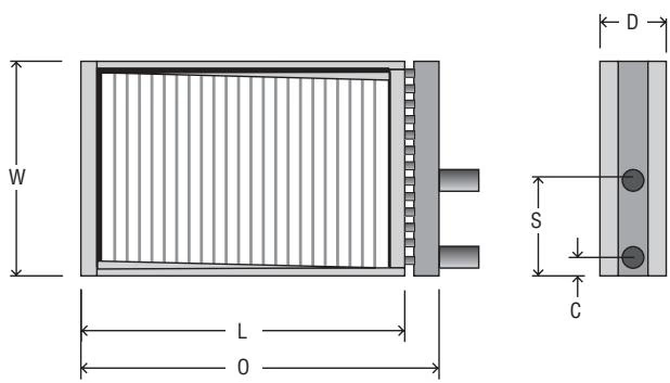
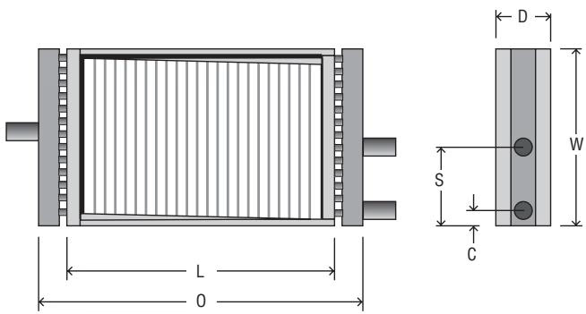
Armstrong Duralite™ 板翅蒸汽盘管 Armstrong Duralite™ Plate Fin Coils connection types

How to Identify the Circuiting and Hand of a Return Bend Coil

Circuiting:

  1. Identify the inlet header and count the number of tubes fed from it.
  2. Count the number of tubes in the face of the coil.
  3. Divide the number of tubes fed from the header by the number of tubes in the face. The result is the identification of the coil's circuit.

Hand:

  1. Face the coil with the airflow at your back.
  2. Point to the outlet connection (top of a liquid coil, closest to you; or condensate return connection on a steam coil, farthest from you).
  3. The connection on your right indicates a right-hand coil; on your left indicates a left-hand coil.

Steam Coils

Armstrong Duralite™ Plate Fin Steam Coils are available in Centifeed, Standard, and Two-Row Return Bend Construction. Centifeed, Standard, and Return Bend coils are made of 5/8" OD tubes as a standard. One-Row coils are available optionally with 1" OD tubes.

WARNING

Depending upon steam flow, long Centifeed coils may require steam to be fed from both ends to eliminate cold tube ends and subsequent freezing potential.
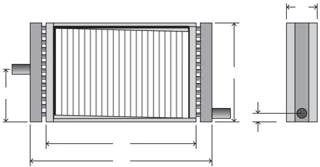
Armstrong Duralite™ 板翅蒸汽盘管 Armstrong Duralite™ Plate Fin Coils standard steam coilsStandard Steam Coils

Armstrong Duralite™ 板翅蒸汽盘管 Armstrong Duralite™ Plate Fin Coils centifeed steam coilsCentifeed Steam Coils

Armstrong Duralite™ 板翅蒸汽盘管 Armstrong Duralite™ Plate Fin Coils centifeed steam coils fed from both endsCentifeed Steam Coils Fed From Both Ends
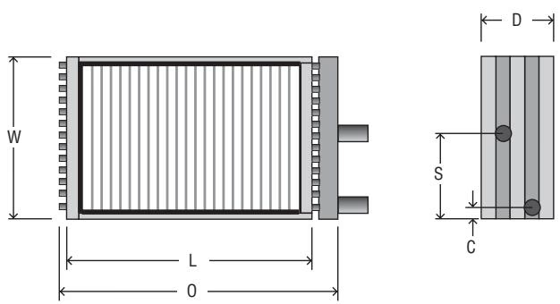
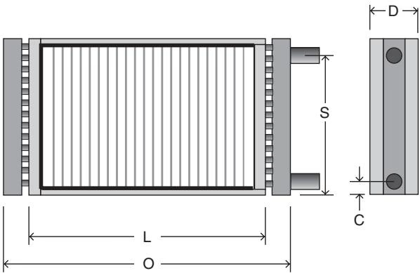
Armstrong Duralite™ 板翅蒸汽盘管 Armstrong Duralite™ Plate Fin Coils return bend steam coilsReturn Bend Steam Coils

Liquid and Cooling Coils

Armstrong Duralite™ Plate Fin Heating Coils are available in Return Header design in one- or two-row configurations and Return Bend design in two or more rows. Liquid coils are made of 5/8" OD copper tube. Cooling coils can be built from 2 to 12 rows and with double, full or 1/2 circuits. Custom circuits are also available.
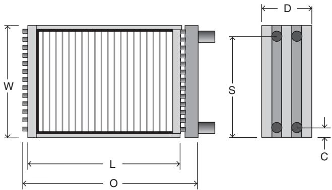
Armstrong Duralite™ 板翅蒸汽盘管 Armstrong Duralite™ Plate Fin Coils liquid and cooling performance

Armstrong Duralite™ 板翅蒸汽盘管 Armstrong Duralite™ Plate Fin Coils return bend heating and cooling coilsReturn Bend Heating & Cooling Coils / Return Header Heating Coils

Installation and Operation

Liquid Coils

  • Install the coils level to ensure complete drainage during shutdown.
  • Supply liquid to the bottom connection and return from the top.
  • Ensure that liquid and air flow through the coil in opposite directions unless instructed otherwise.
  • Support coils and piping individually to prevent undue strains on the connections. Use swing joints or flexible connections.

WARNING

Do not use throttling controls in hot water heating service if there is a possibility of below freezing air passing through the coil. Use a face and by-pass system to control temperature.
Steam Coils

Armstrong Duralite™ 板翅蒸汽盘管 Armstrong Duralite™ Plate Fin Coils steam flow in

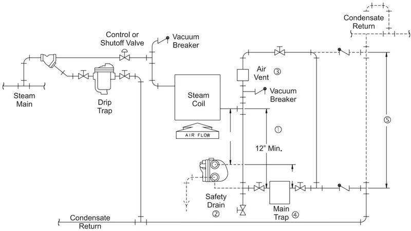
  • Install a drip trap prior to the coils (and before a control valve if there is one) to prevent the introduction of condensate.
  • Install a vacuum breaker in the steam piping prior to the coil to prevent retention of condensate during shutdown. Also install a vacuum breaker on the downstream side of the coils when steam pressure is to be modulated.
  • Vent non-condensable gases individually on each coil to ensure maximum heat transfer and minimum internal corrosion.
  • Trap all coils individually. Use only traps such as the inverted bucket or float and thermostatic which drain continuously.
  • To provide maximum freeze protection, maintain a minimum steam pressure of 5 psig to coils exposed to air temperature below 40°F (5°C).

Armstrong Duralite™ 板翅蒸汽盘管 Armstrong Duralite™ Plate Fin Coils piping practices for steam heating coilsPiping practices for steam heating coils

Steam Trap Selection Guide

EquipmentSelectionsConstant Pressure (0 - 30 psig)Constant Pressure (Above 30 psig)Modulated Pressure (0 - 30 psig)Modulated Pressure (Above 30 psig)
Unit Heaters1st Choice
2nd Choice
IBLV
F&T
IBLV
F&T
F&T
IBLV
F&T
IBLV
Air Handlers1st Choice
2nd Choice
IBLV
F&T
IBLV
F&T
F&T
IBLV
F&T
IBLV
Process Coils1st Choice
2nd Choice
IBLV (0-250 psig)
F&T (0-250 psig)
IBLV (Above 250)
IBLV (Above 250)
F&T
IBLV
F&T
IBLV