Repairable

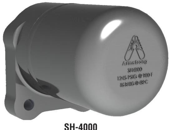
Armstrong SH-4000 Series bimetallic steam traps are designed for superheated steam applications. Features an investment cast stainless steel body, handling up to 1,245 psig (86 bar) and 900°F (482°C).
Armstrong SH-4000 Series Bimetallic Steam Trap is the ideal design for applications involving superheated steam.
During start-up, the bimetallic mechanism is fully open and allows large volumes of non-condensable gases and condensate to be removed from the system. As the system reaches saturated steam conditions, the mechanism begins to close preventing any live steam loss. The superheat during normal operating steam conditions keep the valve closed to ensure long service life.
In the event that operating conditions change and condensate forms at the steam trap inlet, the cooling effect allows the bimetallic mechanism to open and discharge any accumulation. The valve quickly closes once normal operating conditions return.
The SH-4000 consists of an investment cast, stainless steel body that is compact and highly resistant to harsh, corrosive environments. The integral mounting flange is compatible with the Armstrong IS-4, 4-bolt, Class 900, connector making for labor savings and easy steam trap replacement.
| Component | Material |
|---|---|
| Body | ASTM A351 Gr. CF8M Stainless Steel |
| Valve & Seat | Titanium |
| Elements | Ni-Cr Stainless Steel |
| Spiral Wound Gasket | Stainless Steel |
| Bolts | ASTM A193 B7 |
| Weight | 1.7 kg (3.75 lbs) |
Steam traps shall be a bimetallic style designed for superheated steam applications. The steam trap body shall be tamperproof, investment cast stainless steel A351 Gr. CF8M. The mechanism shall consist of a stacked nickel-chrome bimetal operator with titanium valve and seat. The gaskets shall be captured stainless steel spiral wound. The steam trap shall be compatible with the 4-bolt universal connector technology.
NOTE
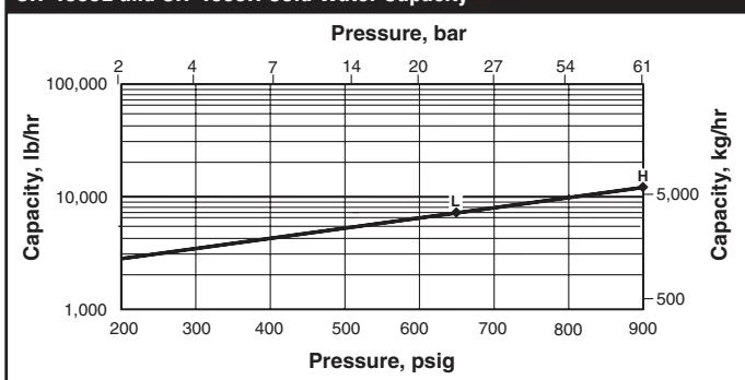
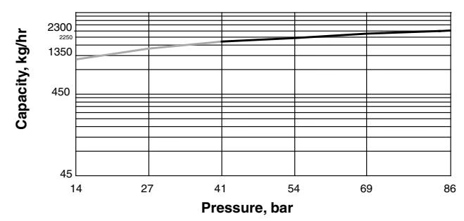
Cold water capacity for start-up loads only. When superheat present, there will be minimal condensate. Grey curve indicates that trap can not be used in this area.
SH-4009L and SH-4009H Cold Water Capacity
SH-4015 Cold Water Capacity
Before installation, verify that the maximum allowable pressure/temperature and maximum operating pressure of the trap are sufficient to handle the system design pressure and temperature. This information can be found on the label located on the trap.
Steam trap installation is critical from both a performance and maintenance aspect. Installation of the trap is simplified if you follow these guidelines:
CAUTION
When working with high pressure/temperature steam, follow safe practices. Superheated steam is invisible. Do not place objects directly in the path of trap discharge.
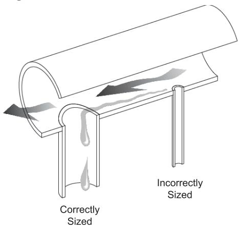
| Steam Main Size | Drip Leg Diameter | Supervised Warm-Up (H) | Automatic Warm-Up (H) |
|---|---|---|---|
| 1/2" (15 mm) | 1/2" (15 mm) | 10" (250 mm) | 28" (700 mm) |
| 3/4" (20 mm) | 3/4" (20 mm) | 10" (250 mm) | 28" (700 mm) |
| 1" (25 mm) | 1" (25 mm) | 10" (250 mm) | 28" (700 mm) |
| 2" (50 mm) | 2" (50 mm) | 10" (250 mm) | 28" (700 mm) |
| 3" (80 mm) | 3" (80 mm) | 10" (250 mm) | 28" (700 mm) |
| 4" (100 mm) | 4" (100 mm) | 10" (250 mm) | 28" (700 mm) |
| 6" (150 mm) | 4" (100 mm) | 10" (250 mm) | 28" (700 mm) |
| 8" (200 mm) | 4" (100 mm) | 12" (300 mm) | 28" (700 mm) |
| 10" (250 mm) | 6" (150 mm) | 15" (375 mm) | 28" (700 mm) |
| 12" (300 mm) | 6" (150 mm) | 18" (450 mm) | 28" (700 mm) |
| 14" (350 mm) | 8" (200 mm) | 21" (525 mm) | 28" (700 mm) |
| 16" (400 mm) | 8" (200 mm) | 24" (600 mm) | 28" (700 mm) |
| 18" (450 mm) | 10" (250 mm) | 27" (675 mm) | 28" (700 mm) |
| 20" (500 mm) | 10" (250 mm) | 30" (750 mm) | 30" (750 mm) |
| 24" (600 mm) | 12" (300 mm) | 36" (900 mm) | 36" (900 mm) |
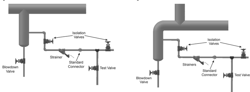
Standard Connector The Standard connector block should be installed in piping with the flow direction stamp pointing in the correct direction as indicated on the connector block.
RECOMMENDATION
Armstrong strongly recommends adding an upstream strainer and isolation valves upstream and downstream of the trap.
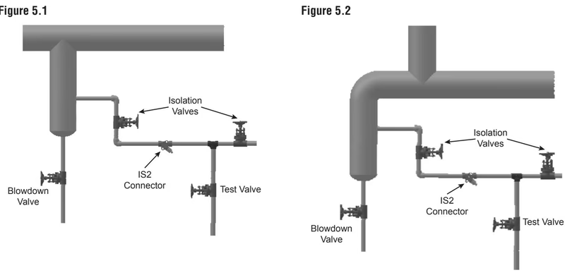
IS2 Connector The IS2 connector block should be installed in piping with the flow direction stamp pointing in the correct direction.
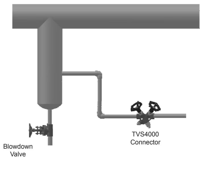
TVS-4000 Connector The TVS-4000/F connector block should be installed in piping with the flow direction stamp pointing in the correct direction. The TVS-4000 has integral strainer and isolation valves.
High pressure drips traps should be tested at least three times per year. When the bimetallic steam trap is suspected of malfunctioning, it can be checked by observing the discharge of the trap. Normal trap operation would be indicated by:
All discharges are accompanied by large amounts of flash steam. Do not confuse the discharge of flash steam with live steam loss. If the trap continues to blow live steam, isolate the trap and repair or replace.
Whenever a trap fails to operate and the reason is not readily apparent, the discharge from the trap should be observed.
1. Cold Trap - No Discharge No condensate or steam coming to trap.
2. Steam Loss If the trap leaks or blows live steam, trouble may be due to any of the following causes:
3. Continuous Flow
If the trap is found defective:
SH-4000: Does not have repair parts. If the trap fails, a new one will need to be installed.
Explore similar products in our catalog