


Up to 99.8% Efficiency

BURKERT 20041978 Type 3361 electromotive globe control valve with G 2 port, DN 50 seat, 24 V DC supply, 0-10 bar operating pressure, PTFE seat seal, SAFEPOS energy pack, and process controller.
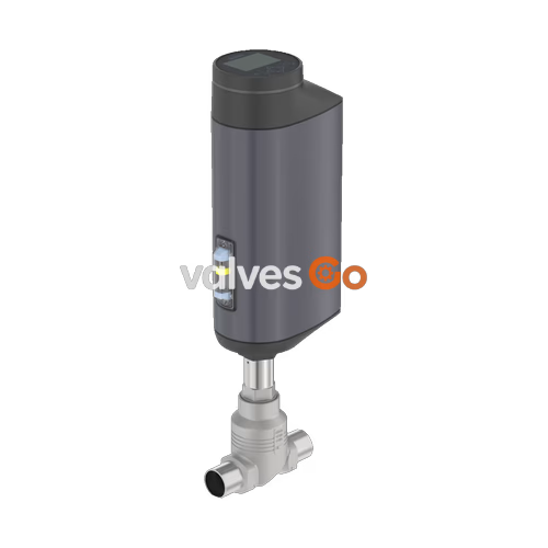
BURKERT 20041978 Type 3361 is an electromotive 2-way globe control valve engineered for high-precision continuous control tasks in process technology. The unit combines an electromotive linear actuator featuring a brushless DC motor and precision ball screw with a flow-optimised stainless steel globe valve body. Configured with a G 2 internal thread connection (DN 50 nominal diameter) and an exchangeable 50 mm valve seat, article 20041978 provides a Kvs value of 37 m³/h and an equal percentage 50:1 control characteristic. Flow direction is directed under the seat (flow direction 2 to 1), preventing pressure shocks and water hammer from interfering with positioning stability.
Actuation force is provided by the AG2 actuator with a 2,500 N positioning drive, maintaining closed-loop control speeds of 4 mm/s with a positioning dead band of ±0.1%. Article 20041978 includes an integrated PID process controller capable of closing process control loops directly on the valve, receiving standard external process sensors (4 to 20 mA, Pt 100, or frequency) without requiring a separate external controller. Fail-safe operation is secured by an integrated SAFEPOS energy-pack emergency storage device, which returns the valve automatically to the normally closed safety position upon supply power failure.
| Parameter | Specification |
|---|---|
| Article Number | 20041978 |
| Valve Type | 3361 |
| Actuator Size | AG2 (Actuator size 2) |
| Motor Positioning Force | 2,500 N |
| Pipeline Connection | G 2 internal thread (DIN ISO 228-1) |
| Nominal Diameter (DN) | DN 50 (NPS 2) |
| Valve Seat Diameter | 50 mm |
| Flow Coefficient Kvs | 37 m³/h (water at +20 °C) |
| Flow Coefficient Cv | 42.8 gal/min |
| Flow Characteristic | Equal percentage 50:1 (DIN EN 60534-2-4) |
| Flow Direction | Under the valve seat (flow 2 → 1) |
| Operating Pressure Range | 0 to 10 bar(g) |
| Nominal Pressure Class | PN 25 (DIN EN 1333) / Class 150 (DIN EN 1759) |
| Medium Temperature Range | -10 °C to +130 °C (recommended for PTFE seat seal) |
| Ambient Temperature Range | -25 °C to +65 °C (see temperature derating limits) |
| Seat Leakage Tightness | Class VI according to DIN EN 60534-4 (bubble-tight soft seal) |
| Maximum Medium Viscosity | Up to 600 mm²/s |
| Supply Voltage | 24 V DC ± 10% (max. 10% residual ripple) |
| Operating Current | Max. 3 A (nominal load + 1 A SAFEPOS charging current); +2 A at min. temp. |
| Standby Power Consumption | 2 to 5 W |
| Duty Cycle | 100% continuous |
| Positioning Speed | 4 mm/s |
| Typical Closing Time | 6.6 s (6,600 ms) |
| Positioning Dead Band | ±0.1% |
| Control Function | Integrated PID process controller |
| Fail-Safe Energy Storage | SAFEPOS energy-pack (factory setting: normally closed) |
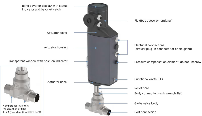
| Local User Interface | Display module with operation keys, configuration menus, 360° LED ring |
| Electrical Connection Type | Terminal strip with cable glands (3 x M20) |
| Digital Service Interface | büS service interface (Bürkert Communicator via USB büS set) |
| Enclosure Ingress Protection | IP65/IP67 (DIN EN 60529), NEMA 4X |
| Cleanability & Hygiene | Ecolab tested (F&E/P3-E No. 40-1), EC Regulation 1935/2004 declaration |
Article 20041978 features an equal percentage control cone with an exchangeable screwed-in valve seat of 50 mm nominal diameter. This configuration yields a theoretical rangeability of 50:1. In the AG2 actuator with 2,500 N drive force, the maximum permissible operating pressure for tight shut-off against flow under the seat is 10 bar(g) with a PTFE seat seal, achieving Class VI seat leakage according to DIN EN 60534-4.
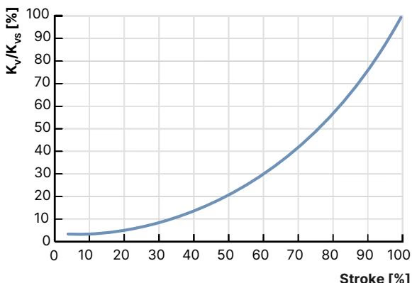
Flow values are measured with water in accordance with DIN EN 60534-2-4 at designated travel strokes:
| Nominal Diameter | Seat Size | Actuator Force | Max. Pressure (Seat Seal) | Theoretical Rangeability | 5% Stroke | 10% Stroke | 20% Stroke | 30% Stroke | 40% Stroke | 50% Stroke | 60% Stroke | 70% Stroke | 80% Stroke | 90% Stroke | 100% Stroke (Kvs) |
|---|---|---|---|---|---|---|---|---|---|---|---|---|---|---|---|
| DN 50 (G 2) | 50 mm | 2,500 N | 10 bar(g) (PTFE, Class VI) | 50:1 | 0.90 m³/h | 1.1 m³/h | 1.9 m³/h | 2.9 m³/h | 4.5 m³/h | 6.8 m³/h | 10.5 m³/h | 15.5 m³/h | 22.0 m³/h | 29.5 m³/h | 37 m³/h |
Flow Direction Note
Type 3361 control valves operate against the closing direction (flow below seat, indicated by numbers 2 → 1 cast onto the valve body). Closing against medium pressure ensures stable throttling and eliminates erratic cone flutter during low-opening conditions.
Every wetted component in article 20041978 complies with the manufacturer declaration for EC Regulation 1935/2004. The valve trim employs an exchangeable seat and control cone design in stainless steel 1.4571 with a soft PTFE seating washer for positive shut-off.
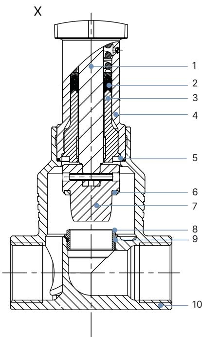
| Item | Component | Material |
|---|---|---|
| 1 | Spindle (Stem) | Stainless steel 1.4401 (316) / 1.4404 (316L) |
| 2 | Spindle Seal Package | PTFE V-seals (filled) with spring compensation |
| 3 | Spindle Guide | Stainless steel 1.4404 (316L) |
| 4 | Packing Gland Tube | Stainless steel 1.4401 (316) |
| 5 | Valve Body Seal | Graphite or PTFE |
| 6 | Seat Seal | PTFE seal washer (leakage class VI) |
| 7 | Control Cone | Stainless steel 1.4571 |
| 8 | Valve Seat (Screwed) | Stainless steel 1.4571 |
| 9 | Valve Seat O-ring | EPDM or PTFE |
| 10 | Valve Body | Cast stainless steel CF3M |
| — | Actuator Housing | Die-cast aluminium, powder-coated |
| — | Actuator Base | Polyphenylene sulphide (PPS) |
| — | Actuator Cover | Polyphenylene sulphide (PPS) |
| — | Display Housing / Blind Cover | Polyphenylene sulphide (PPS) |
| — | Housing Seals | EPDM |
Dimensions are given in millimeters (mm) for the AG2 electromotive actuator and G 2 threaded valve body.
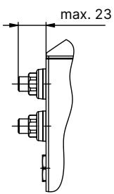
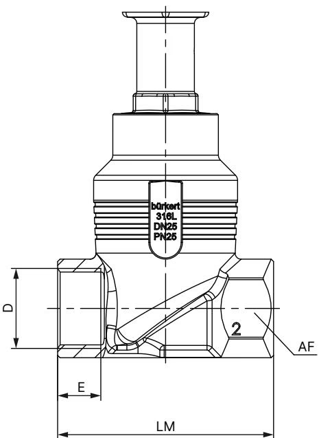
| Nominal Diameter (DN) | Nominal Pipe Size (NPS) | Standard Variant Height H1 [mm] | Fieldbus Variant Height H2 [mm] |
|---|---|---|---|
| DN 10 | NPS 3/8 | 417 | 489 |
| DN 15 | NPS 1/2 | 417 | 489 |
| DN 20 | NPS 3/4 | 423 | 495 |
| DN 25 | NPS 1 | 446 | 518 |
| DN 32 | NPS 1 1/4 | 474 | 546 |
| DN 40 | NPS 1 1/2 | 479 | 551 |
| DN 50 | NPS 2 | 485 | 557 |
Note on height H1/H2: Dimensions are specified without sealing function; the actuator is raised by approximately 2 mm in the fully closed position.
| DN | NPS | Thread D | Thread Depth E [mm] | Face-to-Face Length LM [mm] | Wrench Flat AF [mm] |
|---|---|---|---|---|---|
| DN 10 | NPS 3/8 | G 3/8 | 12 | 65 | 27 |
| DN 15 | NPS 1/2 | G 1/2 | 14 | 65 | 27 |
| DN 20 | NPS 3/4 | G 3/4 | 16 | 75 | 34 |
| DN 25 | NPS 1 | G 1 | 18 | 90 | 41 |
| DN 32 | NPS 1 1/4 | G 1 1/4 | 20 | 110 | 50 |
| DN 40 | NPS 1 1/2 | G 1 1/2 | 22 | 120 | 55 |
| DN 50 | NPS 2 | G 2 | 24 | 150 | 70 |
Article 20041978 is equipped with an integrated PID process controller. An external process transmitter (flow, temperature, pressure, or level sensor) connects directly to the valve actual value input, allowing autonomous closed-loop regulation based on a local or remote set-point.
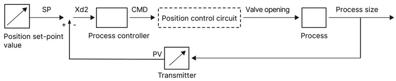
| Input / Output Channel | Technical Parameters |
|---|---|
| Analogue Set-point Input | Galvanically isolated from power supply and analogue output; 0/4 to 20 mA (input resistance 70 Ω); 0 to 5/10 V (input resistance 22 kΩ) |
| Analogue Output | Max. current 10 mA (for voltage output 0 to 5/10 V); load 0 to 800 Ω (for current output 0/4 to 20 mA) |
| Digital Input | 0 to 5 V = log "0", 10 to 30 V = log "1" (invertible via software) |
| Digital Outputs (2 channels) | PNP transistor outputs, current limitation 100 mA each |
| Process Actual Value Input (4 to 20 mA) | Input resistance 70 Ω (80 Ω in auxiliary circuit), 12-bit resolution |
| Process Actual Value Input (Frequency) | Measuring range up to 1,000 Hz, input resistance > 30 kΩ, resolution 0.1% of reading, signal amplitude > 300 mVss (sine, square, triangle) |
| Process Actual Value Input (Pt 100) | Measuring range -20 °C to +220 °C, resolution 0.01 °C, measuring current 1 mA |
| Digital Configuration Interface | büS service interface for connection to PC via USB büS interface set and Bürkert Communicator software Type 8920 |
The actuator cover incorporates an illuminated display module with navigation keys. Users can configure setpoints, tune PID parameters, toggle operating modes between MANUAL and AUTOMATIC, and monitor actual stroke and process values. A 360° LED light ring surrounding the cover provides immediate visual feedback of operating status, fault messages, or travel end positions.
Article 20041978 integrates the SAFEPOS energy-pack module within the AG2 actuator. In the event of an electrical power failure, the energy storage provides instantaneous emergency power to move the valve stem into a defined safety position. For this article, the factory safety position is Normally Closed (NC).
Residual Electrical Energy
Before performing maintenance or opening the actuator housing, switch off the power supply and fully discharge the SAFEPOS energy-pack. Wait until the 360° LED ring goes completely dark; ensure the LED status is not set to "LED off" mode before servicing.
Maximum allowable ambient temperature and process medium temperature are mutually interdependent. Operating at elevated medium temperatures reduces the permissible ambient temperature around the actuator housing.
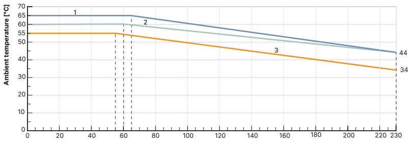
| Seat Seal Material | Leakage Class (DIN EN 60534-4) | Medium Temperature Range | Operating Characteristics |
|---|---|---|---|
| PTFE (soft seal, article 20041978) | Class VI (bubble-tight) | -40 °C to +130 °C (recommended ≤ +130 °C) | Provides tight shut-off without requiring upstream isolation valves. Not recommended for abrasive slurry or severe cavitation. |
| PEEK (soft seal option) | Class VI | -10 °C to +230 °C (recommended > +130 °C) | High-temperature polymer sealing for steam and hot thermal oils. |
| Stainless Steel 1.4571 (metal seal) | Class III / IV | -40 °C to +230 °C | Impervious to erosive conditions; allowable leakage 0.1% to 0.01% of Kvs. Additional shut-off valve recommended. |
Routine maintenance on Type 3361 valves involves servicing the PTFE spindle packing gland, replacing worn control cones, or swapping the screwed-in valve seat.
Mechanical Manual Override Torque Limit
When manually operating the valve using a 3 mm Allen key under de-energized conditions, apply a maximum torque of 2 Nm. Exceeding 2 Nm will damage the internal gear mechanism. Never engage the mechanical override while power is supplied.
| Fastener / Connection Point | Tool Size / Thread | Tightening Torque |
|---|---|---|
| Valve Body Connection (DN 50) | Open-end wrench on body flats | 70 ± 3 Nm (52 ± 2 lbf ft) |
| Screwed Valve Seat (Seat 50 / DN 50) | Installation tool 652609 + torque wrench | 120 + 8 Nm |
| Spindle Guide Bushing (Spindle ø14 mm, DN 50) | Modified socket wrench SW21 | 60 Nm |
| Actuator Base to Housing Screws | T25 hexalobular internal | 5 Nm (crosswise tightening) |
| SAFEPOS Locking Screw | T10 hexalobular internal | 1.1 Nm |
| Display Module Fastening | Manual bayonet lock | Turn clockwise until vertical alignment marks meet |
After replacing a control cone, changing a valve seat, or remounting the actuator onto the valve body, the physical stroke endpoints must be recalibrated by initiating the X.TUNE routine.
Zero Medium Pressure Requirement
Never execute X.TUNE while the valve is under medium pressure. Pressure forces distort stroke detection and result in incorrect positioning calibration. Depressurize and drain the pipeline completely before initiating calibration.
Genuine Bürkert spare part kits and service tools ensure correct sealing performance and mechanical alignment for DN 50 / AG2 assemblies.
| Description | Application / Size | Article Number |
|---|---|---|
| SAFEPOS Energy-Pack Replacement Module | Wearing part for AG2 actuator | 285834 |
| Control Cone Replacement Set (PTFE / Stainless Steel) | Seat 50, DN 50 orifice (includes cone, pin, graphite seal) | 226971 |
| Valve Seat Replacement Set | Seat 50, DN 50 orifice (includes seat, O-ring, graphite seal) | 262179 |
| Seal Set for Spindle Packing Gland | Spindle ø14 mm, DN 25 to DN 50 bodies | 285722 |
| Stainless Steel Spindle Guide Bushing | DN 50 valve body | 246594 |
| Valve Seat Installation Tool | DN 50 valve seat replacement | 652609 |
| Modified Socket Wrench for Packing Gland | Spindle ø14 mm, DN 25 to DN 50 (SW21) | 683223 |
| Body Holding Clamping Device | DN 25 to DN 50 pipe connections | 693771 |
| Replacement Display Module | Plastic housing with keys | 277869 |
| Replacement Blind Cover | Plastic with bayonet lock | 277881 |
| SIM Card Module | Parameter storage and device transfer | 291773 |
| USB büS Interface Set 1 | Includes PC adapter, power supply, terminating resistor, cables | 772426 |
| USB büS Interface Set 2 | Includes PC adapter, terminating resistor, cables | 772551 |
| büS Service Interface Cable Adapter | M12 to Micro-USB (0.3 m) | 774931 |
| M12 Sensor Cable (Process Actual Value X2) | 5-pin, A-coded shielded cable (2 m) | 559177 |
| M12 Signal Cable (Input/Output X1) | 8-pin, A-coded cable (2 m) | 919061 |
| Assembly Lubricant (Klüberpaste UH1 96-402) | Recommended thread lubricant | UH1 96-402 |
Explore similar products in our catalog


