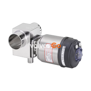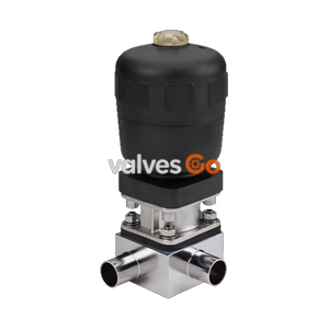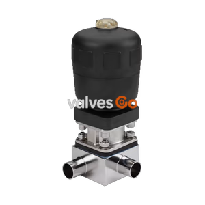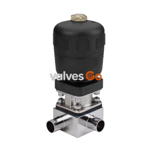
Type 2032

BURKERT 20050340 is a Type 2933 Basic manual diaphragm valve actuator for diaphragm size 20, featuring a stainless steel bonnet, PPS handwheel (Ø45 mm), optical position indicator, and M5x0.5 limit switch ports.
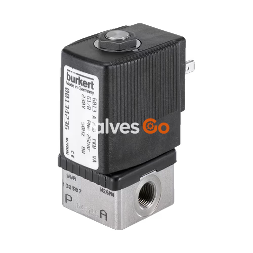
BURKERT 20050340 (Type 2933) is a 2/2-way manually operated diaphragm valve actuator designed for hygienic, sterile, and aggressive process environments. Part of the Type 2933 Basic series, this configuration corresponds to diaphragm size 20 and handwheel size S (Ø45 mm). It features a precision-cast stainless steel 1.4308 diaphragm bonnet paired with a PPS (polyphenylene sulphide) handwheel, enabling continuous service in ambient temperatures from -10 °C to +130 °C (short-term tolerance up to +150 °C) and full autoclave sterilization.
Article 20050340 is delivered as a dedicated actuator assembly module without a pre-assembled valve body or diaphragm seal. It is factory-equipped with an integrated optical position indicator showing a yellow marker with a 30-position rotation scale, a single minimum stroke limiter that acts as an adjustable closing limiter to prevent diaphragm over-compression, and two threaded M5x0.5 bores to mount optional inductive proximity sensors for electrical open/closed position feedback.
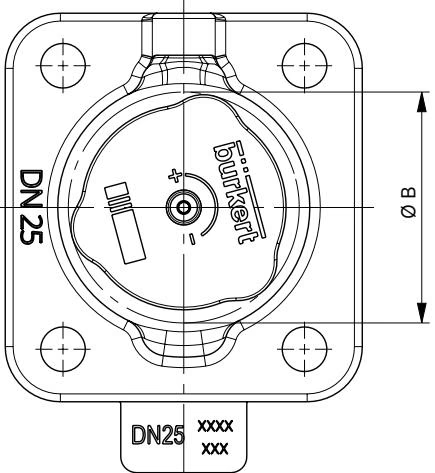
| Specification Parameter | Technical Value / Execution |
|---|---|
| Valve Type / Function | Type 2933 Basic / 2/2-way shut-off |
| Bürkert Part Number (MPN) | 20050340 |
| Diaphragm Size | 20 |
| Handwheel Size / Diameter (Ø B) | Size S / 45 mm |
| Handwheel Elevation per Rotation | 1.75 mm |
| Height in Open Position (H1) | 95 mm |
| Height in Closed Position (H2) | 86 mm |
| Bonnet Material | Stainless steel 1.4308 |
| Handwheel Material | Polyphenylene sulphide (PPS) |
| Valve Spindle Material | Stainless steel 1.4305 |
| Position Indicator Construction | Optical indicator with stroke scale (PA / 1.4305) |
| End Position Detection | Prepared with 2x M5x0.5 threaded bores |
| Actuator Ambient Temperature | -10 °C to +130 °C (short-term up to +150 °C, autoclavable) |
| Permissible Static Medium Pressure | Up to 10 bar |
| Identification | Data matrix code on product label |
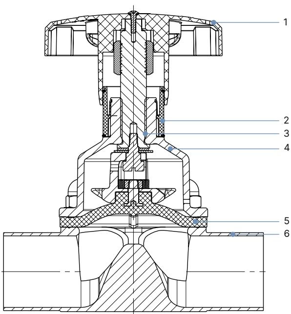
| Item No. | Component | Material Specification in Article 20050340 |
|---|---|---|
| 1 | Handwheel | Polyphenylene sulphide (PPS) |
| 2 | Visual Position Indicator | Polyamide (PA) / Stainless steel 1.4305 |
| 3 | Valve Spindle | Stainless steel 1.4305 |
| 4 | Diaphragm Bonnet | Stainless steel 1.4308 |
| 5 | Diaphragm (compatible options) | EPDM (AD), PTFE/EPDM (EA), advanced PTFE/EPDM (EU), GYLON®/EPDM (ER), FKM (FF) |
| 6 | Valve Body (compatible options) | Forged stainless steel (VS), tube body (VP), cast stainless steel (VG), plastic (PP, PVDF, PVC-U, PVC-C) |
Actuator 20050340 combines with any Bürkert size 20 2-way valve body. The connection geometry and length depend on the selected body manufacturing method and pipe standard:
| Connection Standard | Port DN | Pipe Ext. Ø D1 [mm] | Wall s [mm] | Length L [mm] | h [mm] | H [mm] | Product Key |
|---|---|---|---|---|---|---|---|
| DIN EN ISO 1127 / ISO 4200 (Series B) | DN 15 | 21.3 | 1.6 | 119 | 16.0 | 30.3 | SA42 |
| DIN EN ISO 1127 / ISO 4200 (Series B) | DN 20 | 26.9 | 1.6 | 119 | 16.0 | 30.3 | SA43 |
| DIN 11850 Series 2 / DIN 11866 Series A | DN 20 | 23.0 | 1.5 | 119 | 16.0 | 30.3 | SD43 |
| ASME BPE / DIN 11866 Series C | 3/4" | 19.05 | 1.65 | 117 | 16.0 | 30.3 | SA93 |
| BS 4825 | DN 20 | 19.05 | 1.20 | 117 | 16.0 | 30.3 | SODE |
| Clamp DIN 32676 Series B (ISO pipe) | DN 20 | 26.9 | 1.6 | 114 (D2=50.5) | 16.0 | 30.3 | TC43 |
| Clamp DIN 32676 Series A (DIN pipe) | DN 20 | 23.0 | 1.5 | 119 (D2=34.0) | 16.0 | 30.3 | TD43 |
| Clamp ASME BPE | 3/4" | 19.05 | 1.65 | 102 (D2=25.0) | 16.0 | 30.3 | TG03 |
| Clamp ASME BPE (with variable AF34) | 3/4" | 19.05 | 1.65 | 117 (D2=25.0) | 16.0 | 30.3 | TG03 + AF34 |
| Connection Type / Standard | Nominal Port | Pipe Dimensions | Length L [mm] | h [mm] | H [mm] | Product Key |
|---|---|---|---|---|---|---|
| Welded DIN EN ISO 1127 (Series B) | DN 20 | Ø 26.9 × 1.6 mm | 119 | 17.15 | 30.45 | SA43 |
| Welded ASME BPE (Series C) | 1" | Ø 25.4 × 1.65 mm | 127 | 16.40 | 41.65 | SODF |
| Clamp DIN 32676 Series B (ISO pipe) | DN 20 | Ø 26.9 × 1.6 mm | 119 (D2=50.5) | 17.15 | 42.40 | TC43 |
| Threaded G Connection | G 3/4 | Thread depth 12 mm | 118 (SW 32) | 17.15 | 30.45 | GM85 |
| Threaded NPT Connection | NPT 3/4 | Thread depth 14 mm | 118 (SW 32) | 17.15 | 30.45 | NM85 |
| Threaded Rc Connection | Rc 3/4 | Thread depth 14.5 mm | 118 (SW 32) | 17.15 | 30.45 | RC85 |
| Flanged DIN EN 1092-1 | DN 20 | Flange Ø 105 mm | 150 (L3) | 18.0 | 2.0 | FD23 |
| Flanged ANSI B16.5 | 3/4" (DN 20) | Flange Ø 99 mm | 150 (L3) | 12.7 | 1.6 | FA03 |
| Flanged JIS 10K | DN 20 | Flange Ø 100 mm | 150 (L3) | 14.0 | 1.0 | FJ02 |
| Connection Type / Standard | Port Size | Pipe Ext. Ø D1 [mm] | Length L [mm] | h [mm] | H [mm] | Product Key |
|---|---|---|---|---|---|---|
| Welded DIN EN ISO 1127 (Series B) | DN 20 | 26.9 | 119 | 18.0 | 32.7 | SA43 |
| Welded DIN 11850 Series 2 | DN 20 | 23.0 | 119 | 18.0 | 32.8 | SD43 |
| Welded ASME BPE | 3/4" | 19.05 | 119 | 18.0 | 32.8 | SA93 |
| Welded ASME BPE | 1" | 25.4 | 119 | 18.0 | 32.7 | SODF |
| Clamp DIN 32676 Series A | DN 20 | 23.0 | 119 (D2=34.0) | 18.0 | 32.8 | TD43 |
| Clamp ASME BPE | 3/4" | 19.05 | 117 (D2=25.0) | 18.0 | 25.0 | TG03 |
| Body Material | Connection Style | Nominal Port | Fitting Dimension Ø d | Face-to-Face L1 [mm] | h [mm] | H [mm] | Product Key |
|---|---|---|---|---|---|---|---|
| PP (PP) | Spigot connection | DN 20 | Ø 25 mm | 144 | 17.0 | 42.0 | SS26 |
| PVDF (PD) | Spigot connection | DN 20 | Ø 25 mm | 144 | 17.0 | 36.0 | SS26 |
| PVC-U (PV) | Spigot connection | DN 20 | Ø 25 mm | 144 | 17.0 | 36.0 | KS26 |
| PP (PP) | True union socket | DN 20 | Ø 24.2 mm | 146 (L3=108) | 17.0 | 42.0 | SM26 |
| PVDF (PD) | True union socket | DN 20 | Ø 24.2 mm | 146 (L3=108) | 17.0 | 36.0 | SM26 |
| PVC-U (PV) | True union socket | DN 20 | Ø 25.0 mm | 152 (L3=108) | 17.0 | 36.0 | KM26 |
| PP / PVDF / PVC-U | Flanged connection | DN 20 | Flange 4×14 PCD 75 | 154 (L) | 17.0 | 42 / 36 | FL25 |
Flow rate data represents water flow in m³/h at +20 °C with 4 bar at the valve inlet and 3 bar at the valve outlet:
For diaphragm size 20, the maximum static operating pressure is 10 bar across plastic, forged stainless steel, cast stainless steel, and tube bodies. Adhere to the following handwheel and body bolting torque specifications (+10% tolerance):
| Operating Parameter | Diaphragm: EPDM / FKM | Diaphragm: PTFE / Advanced PTFE / GYLON® |
|---|---|---|
| Max. Permissible Medium Pressure | 10 bar | 10 bar |
| Handwheel Torque for Static Tightness | 0.9 Nm | 3.0 Nm |
| Handwheel Torque for Dynamic Tightness | 2.0 Nm | 4.5 Nm |
| Body Fastening Screws (VS, VG, Plastic bodies) | 4.0 Nm | 4.5 Nm |
| Body Fastening Screws (Tube body VP) | 4.0 Nm | 4.5 Nm |
| Handwheel Retaining Screw Torque | 0.9 Nm | 0.9 Nm |
Tightening Torque Limits
Tightening the handwheel beyond the specified torques reduces diaphragm operating life without improving seal performance. Always tighten the handwheel manually without lever tools.
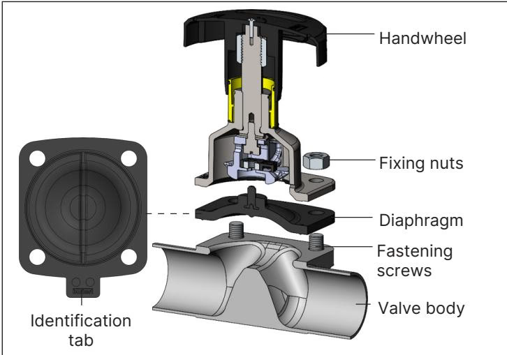
All size 20 diaphragms utilize a bayonet catch for attachment to the actuator spindle compressor:
| Diaphragm Material | Material Code | Bürkert Article Number | Temperature Range | Steam Sterilization Limit |
|---|---|---|---|---|
| EPDM (AD) | EPDM E04 | 693 166 | -10 °C to +143 °C | Max. +150 °C for 60 min |
| FKM (FF) | FKM F01 | 693 167 | 0 °C to +130 °C | Dry heat up to +150 °C (no steam) |
| PTFE / EPDM (EA) | EPDM E04 / PTFE P05 | 20093070 | -10 °C to +130 °C | Max. +140 °C for 60 min |
| Advanced PTFE / EPDM (EU) | EPDM E04 / PTFE P06 | 20093080 | -5 °C to +143 °C | Max. +150 °C for 60 min |
| GYLON® / EPDM Laminate (ER) | PTFE L08 | 693 177 | -5 °C to +130 °C | Max. +140 °C for 60 min |
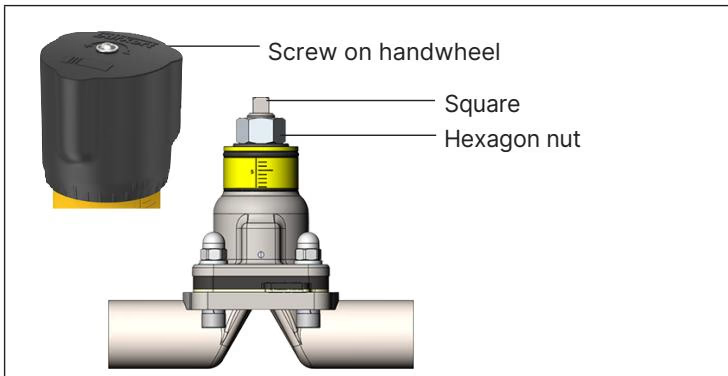
Type 2933 actuator 20050340 includes an adjustable internal minimum stroke limiter implemented via an internal hexagon nut beneath the handwheel:
Adjustment Range
The minimum stroke limiter must be positioned strictly within the 0% to 25% opening stroke range. Do not thread the hexagon nut onto the square portion of the drive spindle.
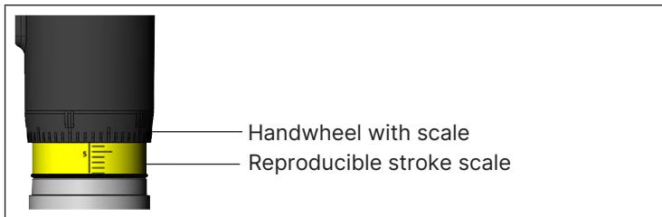
The actuator includes an optical position indicator located below the handwheel. When turning the handwheel counterclockwise to open the valve, a yellow sleeve with an axial millimeter stroke scale emerges. The perimeter of the handwheel carries 30 divisions, allowing fine verification of valve opening stroke.

The stainless steel bonnet of article 20050340 contains two M5x0.5 threaded bores for direct mounting of inductive proximity switches:
To configure electrical feedback, screw the inductive sensor into the respective port (upper port for OPEN, lower port for CLOSED) until it detects the internal metallic compressor plate, then secure the sensor locknut.
Self-Draining Alignment
Mount the valve assembly with the actuator oriented upright or angled according to the self-draining angle marked on forged (VS) or tube (VP) bodies. Ensure the leak detection relief bore on the diaphragm bonnet points toward the lowest elevation.
Explosion Protection Compliance (Variable PX51)
When combined with ATEX/IECEx certified assemblies under variable code PX51 (EPS 18 ATEX 2 008 X / IECEx EPS 18.0007X), the actuator qualifies as Category 2 mechanical equipment for Zones 1/21 and 2/22 (Ex h IIC T4...T2 Gb / Ex h IIIC T135 °C...T300 °C Db). Ground the valve body to the piping system. If installed on a non-conductive plastic body, connect the actuator bonnet to earth via a dedicated grounding strap. Clean external surfaces only with a damp or anti-static cloth to prevent electrostatic charge generation.
Explore similar products in our catalog