


Up to 99.8% Efficiency

BURKERT 20052006 (Type 3361) is a 24 V DC electromotive globe control valve with DN20 PN25 flanges, AG2 1300 N linear actuator, 3.2 m³/h Kvs, and SAFEPOS electrical energy storage for fail-safe closing.
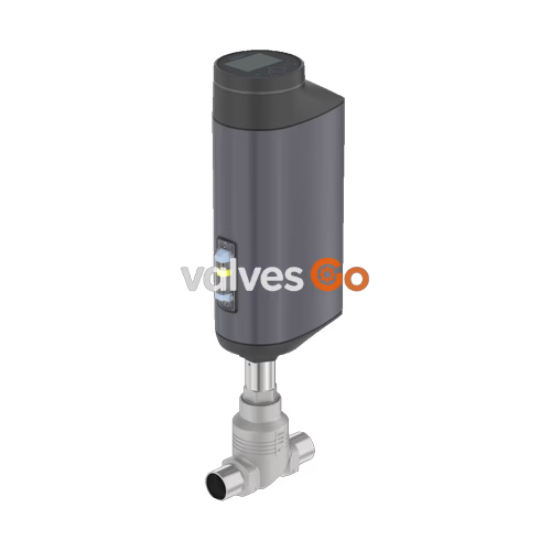
BURKERT 20052006 (Type 3361) is an electromotive 2-way globe control valve engineered for high-precision continuous fluid regulation in demanding process environments. The unit integrates an AG2 brushless DC electric linear actuator driving a precision ball screw mechanism that provides 1300 N positioning force at a linear speed of 6 mm/s. Fluidic control is delivered through a DN 20 flanged valve body cast in CF3M stainless steel, fitted with a 10 mm (3/8") seat diameter and an equal-percentage control cone offering a 50:1 theoretical rangeability. Rated for operating pressures from 0 to 25 bar(g), this valve configuration features a nominal Kvs flow coefficient of 3.2 m³/h (Cv 3.7 gpm) under flow-below-seat conditions (2 → 1). An integrated SAFEPOS electrical energy storage pack guarantees emergency fail-safe closure to the normally closed status upon loss of line power without relying on mechanical return springs.
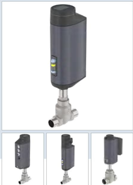
Operating parameters and electromechanical performance values for BURKERT 20052006 (Type 3361) are summarized below:
| Parameter | Specification |
|---|---|
| Valve Type | Electromotive 2-way globe control valve (Type 3361) |
| Article Number | 20052006 |
| Nominal Port Diameter | DN 20 (NPS 3/4) |
| Port Connection Type | Flange DIN EN 1092-1, FTF 1 per DIN EN 558-1 |
| Nominal Pressure Class | PN 25 (DIN EN 1333) / Class 150 (DIN EN 1759) |
| Operating Pressure Range | 0 to 25 bar(g) |
| Seat Orifice Diameter | 10 mm (3/8") |
| Flow Coefficient Kvs / Cv | 3.2 m³/h / 3.7 gpm (water, DIN EN 60534-2-4) |
| Flow Characteristic | Equal percentage, 50:1 theoretical rangeability |
| Flow Direction | Below seat (against closing direction, port 2 → 1) |
| Seat Seal / Leakage Rating | Metallic stainless steel 1.4571 / Class IV (DIN EN 60534-4) |
| Actuator Size / Drive Force | AG2 / 1300 N nominal thrust |
| Linear Travel Speed | 6 mm/s |
| Typical Closing Time | 3.3 s (3300 ms) |
| Positioning Dead Band | ±0.1% |
| Supply Voltage | 24 V DC ±10% (residual ripple max. 10%) |
| Operating Current | Max. 3 A at max. load (includes 1 A SAFEPOS charging current); +2 A at min. temp |
| Standby Power Consumption | 2 to 5 W |
| Duty Cycle | 100% continuous |
| Protection Class | Class III (DIN EN 61140) |
| Ingress Protection | IP65 / IP67 (DIN EN 60529), NEMA 4X |
| Medium Temperature Range | -10 °C to +185 °C (system limits -40 °C to +230 °C) |
| Ambient Temperature Range | -25 °C to +65 °C (subject to module derating) |
| Maximum Fluid Viscosity | Up to 600 mm²/s |
BURKERT Type 3361 fulfills strict European and international requirements for sanitary, industrial, and explosion-protected service:
Component materials have been selected to resist industrial washdowns, chemical corrosion, and mechanical vibration. Wetted metallic parts are constructed from molybdenum-bearing austenitic stainless steels.
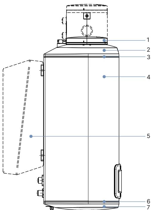
| Item | Actuator Component (AG2) | Standard Material |
|---|---|---|
| 1 | Display housing / Blind cover | Polyphenylene sulphide (PPS); Stainless steel 1.4301 for ATEX/IECEx |
| 2 | Actuator cover | Polyphenylene sulphide (PPS) |
| 3, 6 | Housing seals | EPDM |
| 4 | Actuator housing | Cast aluminium, powder-coated |
| 7 | Actuator base | Polyphenylene sulphide (PPS) |
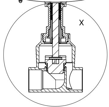
| Item | Valve Body Component | Standard Material |
|---|---|---|
| 1 | Spindle (Stem) | Stainless steel 1.4401 (316) / 1.4404 (316L) |
| 2 | Spindle seal | Filled PTFE V-rings with Belleville spring compensation |
| 3 | Spindle guide | Stainless steel 1.4404 (316L) |
| 4 | Packing gland tube | Stainless steel 1.4401 (316) |
| 5 | Valve body seal | Graphite or PTFE |
| 6 | Seat seal | Stainless steel 1.4571 (optionally hardened); soft PTFE or PEEK optional |
| 7 | Control cone | Stainless steel 1.4571 (optionally hardened) |
| 8 | Valve seat (screwed-in) | Stainless steel 1.4571 (optionally hardened) |
| 9 | Valve seat O-ring | EPDM or PTFE |
| 10 | Valve body | Cast stainless steel CF3M |
Actuator heights and body face-to-face dimensions for the DN 20 flanged configuration are detailed below in millimeters:
| Port Size DN | Actuator Size | Height H1 (Standard Display) | Height H2 (Fieldbus Gateway Variant) |
|---|---|---|---|
| DN 10 | AG2 | 417 mm | 489 mm |
| DN 15 | AG2 | 417 mm | 489 mm |
| DN 20 | AG2 | 423 mm | 495 mm |
| DN 25 | AG2 | 446 mm | 518 mm |
| DN 32 | AG2 | 474 mm | 546 mm |
| DN 40 | AG2 | 479 mm | 551 mm |
| DN 50 | AG2 | 485 mm | 557 mm |
Actuator Height Clearance
In the fully closed seated position, the actuator is raised by approximately 2 mm without sealing function deformation. Maintain adequate overhead clearance for servicing.
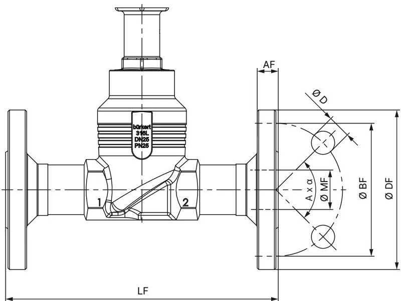
| Port DN | Face-to-Face LF | Flange Outer Ø DF | Bolt Circle Ø BF | Flange Thickness AF | Hole Ø D | Pattern A × α | Chamfer Ø MF |
|---|---|---|---|---|---|---|---|
| DN 10 | 130 mm | 90 mm | 60 mm | 16 mm | 14 mm | 4 × 90° | 13.6 mm |
| DN 15 | 130 mm | 95 mm | 65 mm | 16 mm | 14 mm | 4 × 90° | 18.1 mm |
| DN 20 | 150 mm | 105 mm | 75 mm | 18 mm | 14 mm | 4 × 90° | 23.7 mm |
| DN 25 | 160 mm | 115 mm | 85 mm | 18 mm | 14 mm | 4 × 90° | 29.7 mm |
| DN 32 | 180 mm | 140 mm | 100 mm | 18 mm | 18 mm | 4 × 90° | 38.4 mm |
| DN 40 | 200 mm | 150 mm | 110 mm | 18 mm | 18 mm | 4 × 90° | 44.3 mm |
| DN 50 | 230 mm | 165 mm | 125 mm | 20 mm | 18 mm | 4 × 90° | 56.3 mm |
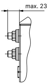
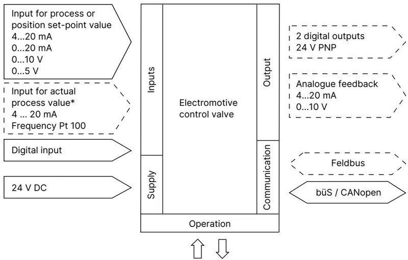
BURKERT 20052006 incorporates an analog setpoint interface with digital status I/O, local operating keys, and a büS service connection for parameterization via the Bürkert Communicator software. Terminal connections are housed under cable feed-through bushings, with circular M12 connectors available for external wiring.
| Signal Type | Terminal / Connector Spec | Technical Characteristics |
|---|---|---|
| Analog Setpoint Input | X1 (Pins 7, 8) | Galvanically isolated from supply and analog output: 0/4 to 20 mA (70 Ω input impedance) or 0 to 5/10 V (22 kΩ input impedance) |
| Analog Feedback Output | X1 (Pins 5, 6) | Max. 10 mA for 0 to 5/10 V output; load 0 to 800 Ω for 0/4 to 20 mA current output |
| Digital Input | X1 (Pins 1, 2) | 0 to 5 V = logic "0", 10 to 30 V = logic "1"; inverted logic configurable |
| Digital Outputs (2x) | X1 (Pins 2, 3, 4) | PNP transistor outputs, current-limited to 100 mA each |
| Power Supply & büS | X3 (Pins 1 to 5) | Pin 1: CAN Shield; Pin 2: +24 V DC ±10%; Pin 3: GND / CAN_GND; Pin 4: CAN_H; Pin 5: CAN_L |
| Communication Protocol | Service-büS | CANopen-based Bürkert system bus via micro-USB adapter or USB-büS stick |
The valve features an equal-percentage flow characteristic curve conforming to DIN EN 60534-2-4. Under flow-below-seat orientation (flow direction 2 → 1), media pressure dampens closure transients and eliminates hydraulic chatter.
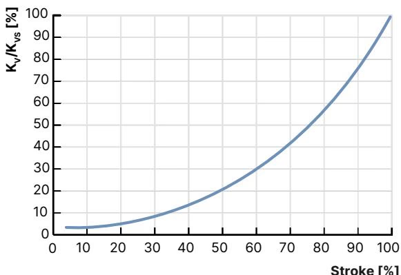
Flow rates as a function of valve stroke for DN 20 bodies across available seat sizes are presented below:
| Port DN | Seat Size | Actuator Force | Max. Working Pressure | Rangeability | Kv at 10% | 20% | 30% | 40% | 50% | 60% | 70% | 80% | 90% | Kvs (100%) |
|---|---|---|---|---|---|---|---|---|---|---|---|---|---|---|
| DN 20 | 10 | 1300 N | 25 bar (IV) | 50:1 | 0.12 | 0.16 | 0.20 | 0.33 | 0.52 | 0.77 | 1.2 | 1.8 | 2.6 | 3.2 m³/h |
| DN 20 | 15 | 1300 N | 25 bar (IV) | 50:1 | 0.14 | 0.17 | 0.22 | 0.35 | 0.52 | 0.80 | 1.2 | 1.8 | 2.9 | 5.2 m³/h |
| DN 20 | 20 | 1300 N | 25 bar (VI) | 50:1 | 0.20 | 0.25 | 0.30 | 0.45 | 0.70 | 1.1 | 1.6 | 2.4 | 3.5 | 7.1 m³/h |
Pressure retention adheres to DIN EN 12516-1 standards for PN 25 piping systems. Operating boundaries are governed simultaneously by line pressure, fluid temperature, and environmental heat dissipation.
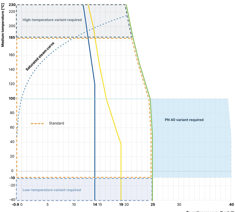
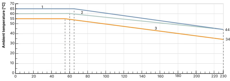
Seat material characteristics determine achievable shut-off tightness and operating thermal spans:
Type 3361 AG2 features a compact, fully enclosed mechanical assembly designed to prevent liquid pooling and dust ingress.
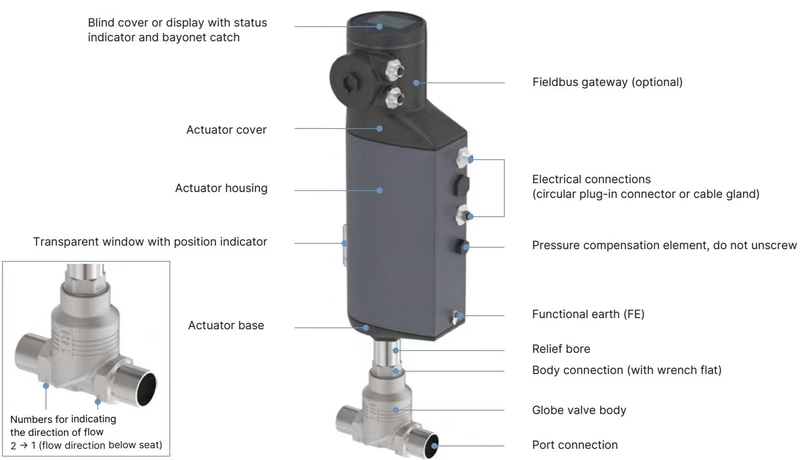
Key physical features include:
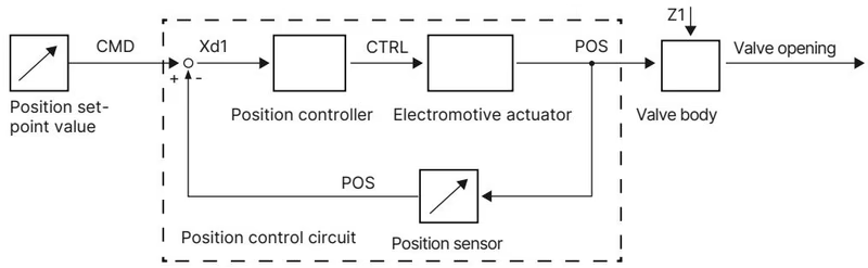
Closed-Loop Position Control
The internal non-contact displacement sensor measures the real-time linear stroke (POS) of the drive shaft. The internal microprocessor compares POS against the setpoint command (CMD) and actuates the motor via pulse-width variable CTRL, providing dynamic accuracy within a ±0.1% dead band.
Routine maintenance of Type 3361 involves periodic inspection of the gland relief bore and replacement of wear components using original Bürkert kits.
Depressurize and Open Valve Prior to Disassembly
Before loosening body connections, isolate line pressure, vent the pipe, and ensure the valve is driven to at least 1/3 open position in MANUAL mode. Unscrewing the actuator while the control cone is seated will permanently deform the trim.
X.TUNE Calibration Restriction
Never initiate the automatic X.TUNE stroke adaptation under line pressure. Running X.TUNE while fluid pressure is applied causes severe position calibration errors and erratic process operation.
| Joint / Component | Connection Size | Required Tightening Torque |
|---|---|---|
| Valve Body to Actuator Connection | DN 20 Body | 50 ± 3 Nm (37 ± 2 lbf ft) |
| Screwed-in Valve Seat | Seat Size 10 (DN 20 body) | 28 +3 Nm |
| Spindle Guide Bushing | Spindle Ø 10 mm (DN 20) | 25 Nm |
| Actuator Cover Fasteners | T25 Torx screws | 5 Nm |
| Mechanical Manual Override | 3 mm Hex key | Max. 2 Nm limit |
| SAFEPOS Locking Screw | T10 Torx screw | 1.1 Nm |
| Component Description | Variant / Application | Order Number |
|---|---|---|
| Control Cone Set (Steel/Steel) | Seat Size 10 / DN 20 Body | 149 914 |
| Valve Seat Set (with Graphite Gasket) | Seat Size 10 / DN 20 Body | 262 151 |
| Packing Gland Seal Set | Spindle Ø 10 mm, DN 15 to DN 20 | 285 685 |
| Stainless Steel Spindle Guide | Spindle Ø 10 mm, DN 20 Body | 246 578 |
| SAFEPOS energy-pack Module | AG2 Actuator Wear Part | 285 834 |
| Seat Installation Tool | DN 20 Valve Body | 652 605 |
| Modified Socket Wrench (Packing Gland) | Spindle Ø 10 mm, DN 20 Body (SW21) | 683 222 |
| USB büS Interface Stick Set 1 | Includes power pack, terminator, Y-adapter | 772 426 |
| Pipe Holding Bracket Tool | DN 15 to DN 20 Line Connections | 693 770 |
Explore similar products in our catalog


