


Up to 99.8% Efficiency

Burkert 20061314 (Type 3280) is an electromotive 2-way globe proportional valve with G 1/4 brass body, DN 1.5 orifice, PEEK/EPDM seal, 24 V DC power supply, 0-15 bar operating pressure, and PWM control.
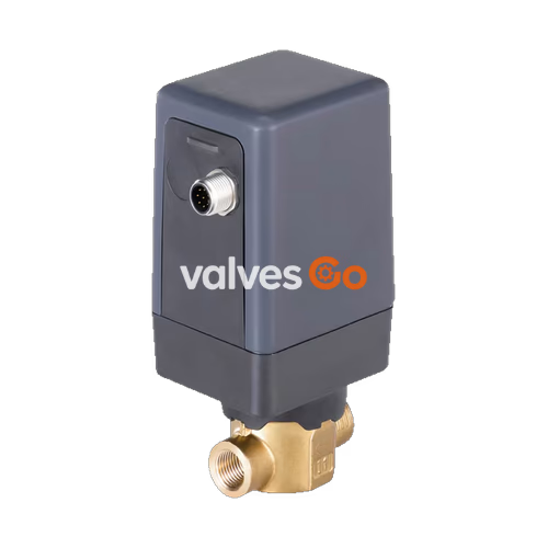
BURKERT 20061314 (Type 3280) is an electromotive direct-acting 2-way globe proportional control valve designed for dosing neutral liquids and gases in open or closed control loops. Driven by a linear stepper motor via a threaded spindle, the valve continuously repositions a parabolic control cone against media flow entering below the valve seat. Article 20061314 features a G 1/4 threaded brass body, a 1.5 mm nominal seat diameter (Kv 0.065 m³/h), a PEEK seat seal backed by EPDM elastomer, and an integrated electronic assembly operating from 24 V DC.
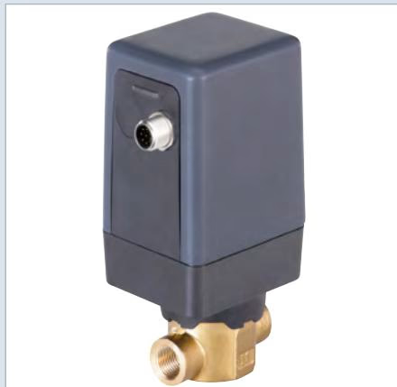
Maintaining a set valve position does not require motor power; holding power drops below 1 W once positioned. The unit responds to an 800 Hz PWM set-point command and provides a PNP digital output signal confirming the fully closed end position.
| Parameter | Value |
|---|---|
| Article Number | 20061314 |
| Model Family | Type 3280 |
| Design | Electromotive 2-way direct-acting globe control valve |
| Port Connection | G 1/4 internal thread (EN ISO 228-1) |
| Seat Orifice DN | 1.5 mm (1/16") |
| Kv Value (Water, +20 °C, Δp = 1 bar) | 0.065 m³/h |
| Flow Direction | Under seat (flow against closing direction) |
| Operating Pressure Range | 0...15 bar(g) for fluid media; 0...22 bar(g) for gaseous media |
| Supply Voltage | 24 V DC ±10% (max. residual ripple 10%) |
| Power Consumption | < 1 W holding position; max. 12 W (high-pressure variant) |
| Set-point Input Signal | PWM signal (800 Hz, 24 V logic level, min. 10 V, max. 30 V) |
| Digital Feedback Output | PNP, max. 100 mA current limit, active when valve is closed |
| Actuating Time (0...100% stroke) | Approx. 2.5 s (normal speed) / 5 s (slow speed) |
| Dead Band | ±0.5% of end value (setting range 1:100) |
| Duty Cycle | Up to 100% (subject to ambient temperature derating) |
| Medium Temperature Range | 0 °C...+70 °C |
| Permissible Ambient Temperature | -10 °C...+50 °C (for high-pressure specification) |
| Max. Medium Viscosity | 600 mm²/s (cSt) |
| Degree of Protection | IP54 (with suitable connected cable plug) |
| Weight | Approx. 0.7 kg |
The actuator housing isolates electronic and electromechanical components from the process medium. Linear force is delivered by the stepper motor via an internal threaded spindle coupled to the valve stem.
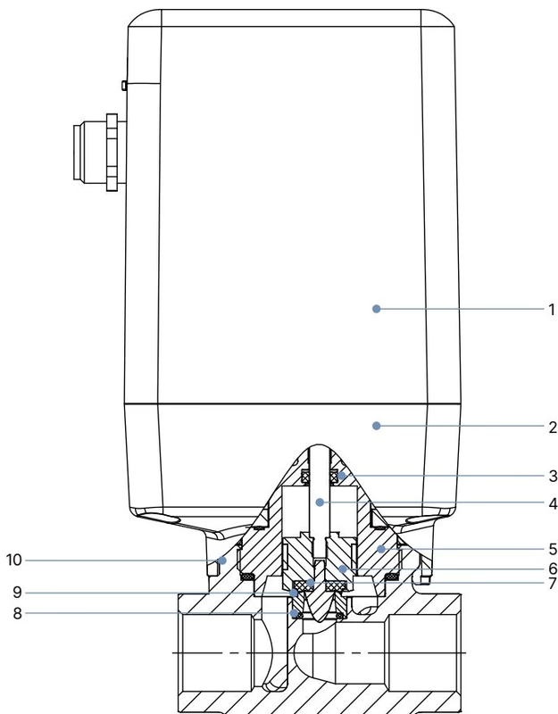
| Item No. | Component | Material |
|---|---|---|
| 1 | Actuator Housing Cover | Polycarbonate (PC GF10) |
| 2 | Actuator Housing Base | Polyphenylene sulphide (PPS GF40) |
| 3 | Stem Seal | EPDM / FKM / NBR |
| 4 | Spindle | Stainless steel 1.4305 |
| 5 | Upper Valve Body | Brass |
| 6 | Piston with Parabolic Control Element & Guiding Shaft | Stainless steel 1.4305 / PTFE |
| 7 | Seat Seal | PEEK (seat size 1.5 mm) backed by EPDM |
| 8 | O-ring | EPDM |
| 9 | Valve Seat | Stainless steel 1.4301 / 1.4305 |
| 10 | Valve Body | Brass |
Seat Tightness Note for Seat Size 1.5 mm
For seat sizes 1.0 mm and 1.5 mm, PEEK seat seals are used instead of soft elastomeric discs. The seat tightness of the valve is consequently lower compared to pure elastomer seals.
Electrical connection is established through an 8-pin A-coded M12 circular male connector located on the actuator base. Input/output signals share supply potential without galvanic isolation.
| M12 Pin | Wire Color (Cable 919061) | Configuration | Function / Signal Level |
|---|---|---|---|
| 1 | White | Supply + | 24 V DC ±10%, max. residual ripple 10% |
| 2 | Brown | Supply GND | 24 V DC GND |
| 3 | Green | Internal use | Do not connect; insulate wire |
| 4 | Yellow | Internal use | Do not connect; insulate wire |
| 5 | Grey | Internal use | Do not connect; insulate wire |
| 6 | Pink | Set-point input + | PWM input (800 Hz) / 4...20 mA / 0...10 V |
| 7 | Blue | Digital output | PNP, 0...5 V (log. 0), 10...30 V (log. 1, closed) |
| 8 | Red | Signal GND | Signal reference GND |
| Body | Shield | Shielding | Connected to valve body |
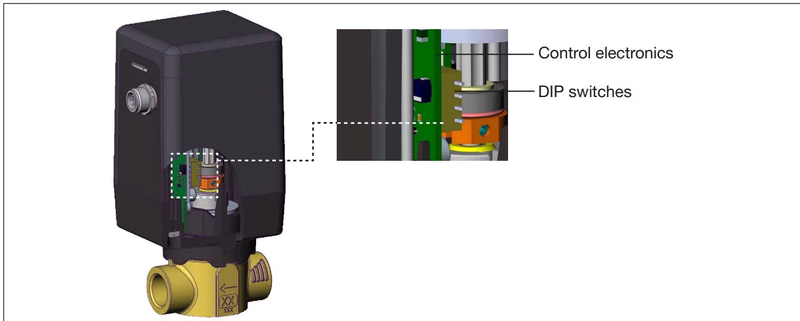
Configuration parameters are accessible via a 4-pole internal DIP switch block on the electronics board after loosening the actuator housing cover:
| DIP Switch | Position | PWM Version Function | Standard Analog Function |
|---|---|---|---|
| 1 | OFF | Increasing: 0...100% PWM duty cycle corresponds to 0...100% stroke | Normal: 4...20 mA corresponds to 0...100% stroke |
| 1 | ON | Decreasing: 100...0% PWM duty cycle corresponds to 0...100% stroke | Reversal: 20...4 mA corresponds to 0...100% stroke |
| 2 | OFF | No function | Set-point input 4...20 mA |
| 2 | ON | No function | Set-point input 0...10 V |
| 3 | OFF | Actuating speed normal (0...100% in 2.5 s) | Actuating speed normal (0...100% in 2.5 s) |
| 3 | ON | Actuating speed slow (0...100% in 5.0 s) | Actuating speed slow (0...100% in 5.0 s) |
| 4 | OFF | Low power mode: OFF | Low power mode: OFF |
| 4 | ON | Low power mode: ON (reduced holding force/heating) | Low power mode: ON (reduced holding force/heating) |
Low Power Mode Pressure Restriction
Activating DIP switch 4 reduces motor drive current, lowering operating heat. This setting must only be enabled when differential pressure across the valve does not exceed 1 bar and maximum media pressure does not exceed 3 bar. Exceeding these limits will cause positioning failure.
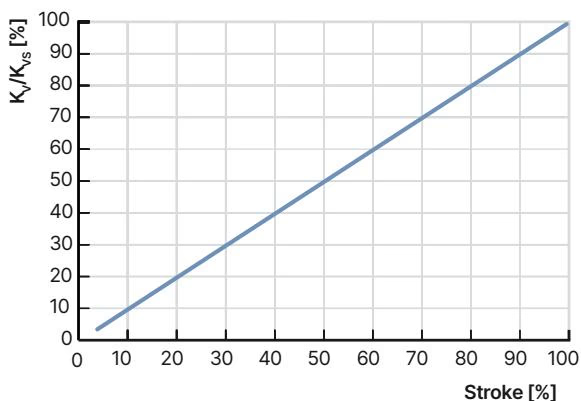
The motor valve produces a linear operating characteristic when sized properly relative to total circuit friction.
| Orifice Seat Size (mm) | Port Connection | Kvs Value (m³/h) | Standard Pressure Range (bar) | High-Pressure Liquids (bar) | High-Pressure Gases (bar) |
|---|---|---|---|---|---|
| 1.0 | G 1/4 | 0.030 | 0...6 | 0...15 | 0...22 |
| 1.5 (20061314) | G 1/4 | 0.065 | 0...6 | 0...15 | 0...22 |
| 2.0 | G 1/4, G 3/8 | 0.130 | 0...6 | 0...15 | 0...22 |
| 3.0 | G 1/4, G 3/8 | 0.300 | 0...6 | 0...15 | 0...22 |
| 4.0 | G 3/8 | 0.500 | 0...6 | 0...12 | 0...12 |
| 5.0 | G 3/8 | 0.750 | 0...6 | 0...12 | 0...12 |
| 6.0 | G 3/8 | 0.900 | 0...6 | 0...15 | 0...16 |
| 8.0 | G 1/2 | 1.500 | 0...6 | 0...12 | 0...12 |
| 10.0 | G 1/2 | 1.900 | 0...6 | 0...10 | 0...10 |
Flow Calculation and Seat Dimensioning
Select the seat diameter so that valve pressure drop represents at least 25% of the total system pressure loss (Δp_valve > 0.25 · Δp_total). A smaller pressure drop causes the linear characteristic to deform into a non-linear system response.
| Flow Condition | Liquids Kv [m³/h] | Gases Kv [m³/h] |
|---|---|---|
| Sub-critical: $p_2 > \frac{p_1}{2}$ | $Q \cdot \sqrt{\frac{\rho}{1000 \cdot \Delta p}}$ | $\frac{Q_N}{514} \cdot \sqrt{\frac{T_1 \cdot \rho_N}{p_2 \cdot \Delta p}}$ |
| Supercritical: $p_2 < \frac{p_1}{2}$ | $Q \cdot \sqrt{\frac{\rho}{1000 \cdot \Delta p}}$ | $\frac{Q_N}{257 \cdot p_1} \cdot \sqrt{T_1 \cdot \rho_N}$ |
Motor duty cycle designates the operational active running time of the stepper drive, not the continuous energized duration of the electronic assembly.
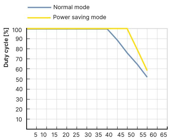
Operating above recommended duty cycle percentages causes thermal overload. At an ambient temperature of +50 °C, the permissible motor duty cycle for standard seats DN 1...6 is derated, requiring lower continuous cycling rates.
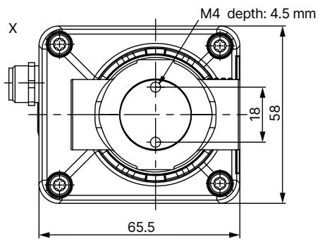
Dimensions for threaded body variants in millimetres:
| Port D | A (NPT) | B (NPT) | C (G thread) | Dimension E (mm) | Dimension F (mm) | Dimension G (mm) | Dimension H (mm) |
|---|---|---|---|---|---|---|---|
| G 1/4 (20061314) | — | — | 12 | 96.4 | 134.2 | 10 | 27.5 |
| NPT 1/4 | 5.8 | 10.0 | — | 96.4 | 134.2 | 10 | 27.5 |
| G 3/8 | — | — | 12 | 97.4 | 137.2 | 12 | 27.5 |
| NPT 3/8 | 6.0 | 10.3 | — | 97.4 | 137.2 | 12 | 27.5 |
| G 1/2 | — | — | 14 | 97.4 | 139.2 | 14 | 29.5 |
| NPT 1/2 | 8.2 | 13.7 | — | 97.4 | 139.2 | 14 | 29.5 |
During an interruption of electrical power, Type 3280 retains its instantaneous physical position. Moving to a fail-safe position requires an external capacitive buffer module.
| Accessory Description | Specification / Function | Article No. |
|---|---|---|
| Capacitive Buffer Module Type 1573 | Supplies 18 V DC backup for several seconds upon power failure to drive valve closed | 773440 |
| Power Supply Unit Phoenix Class 2 | 85...240 V AC / 24 V DC, 1.25 A, NEC Class 2 (UL 1310) | 772438 |
| Power Supply Unit for DIN Rail | 100...240 V AC / 24 V DC, 1.0 A, NEC Class 2 | 772361 |
| Power Supply Unit for DIN Rail | 100...240 V AC / 24 V DC, 2.0 A, NEC Class 2 | 772362 |
| Power Supply Unit for DIN Rail | 100...240 V AC / 24 V DC, 3.8 A, NEC Class 2 | 772898 |
| M12 Shielded Cable Socket, 8-pin | Cable length: 2 m, flying leads for analog/digital I/O | 918991 |
| M12 Unshielded Cable Socket, 8-pin | Cable length: 2 m, flying leads for analog/digital I/O | 919061 |
Mount the valve preferably in an upright vertical position with the actuator cover pointing upwards. The flow direction must correspond to the arrow on the brass body (fluid entering under the seat).
Upstream Media Filtration
Solid particulates in the fluid stream can cause seat leakage or mechanical blockage. Install an upstream dirt filter with a mesh width ≤ 0.3 mm before the valve inlet.
When tightening port fittings, apply wrench counterforce only to the brass valve body flats. Never use the plastic actuator housing as a lever arm. Clean housing surfaces with damp cloths and neutral detergents; alkaline cleaning agents must not be used on PPS or PC components.
Explore similar products in our catalog


