Up to 99.8% Efficiency

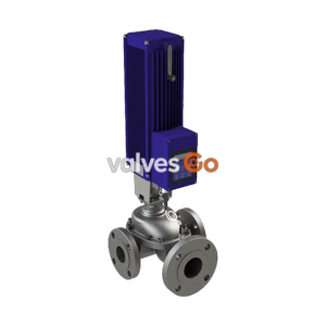
Bürkert Type 3361 (SKU 20063186) electromotive 2-way globe control valve. Features highly precise dynamic control, up to 6 mm/s positioning speed, and IP65/IP67 protection.
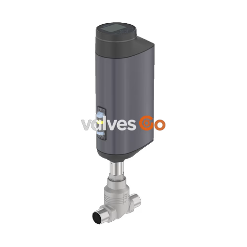
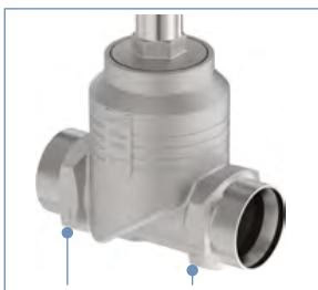
The Bürkert 20063186 (Type 3361) is an innovative electromotive 2-way globe control valve designed for demanding operating conditions. Equipped with a ball screw actuator, it positions the control cone with exceptional precision at speeds up to 6 mm/s, reacting almost delay-free to process signals. The flow-optimized valve body can be fitted with various valve seats for precise adaptation to customer needs. Its robust, IP65/IP67-rated hygienic design ensures easy cleaning and resistance to harsh environments, shocks, and vibrations. The fieldbus-compatible Type 3361 provides advanced functions for process monitoring, valve diagnostics, and predictive maintenance.
| Feature | Specification |
|---|---|
| Design | Globe control valve |
| Nominal diameter | DN 10 to DN 100 (NPS 3/8 to 4) |
| Flow direction | Against closing direction (below seat) |
| Operating pressure | 0 to 25 bar(g), 40 bar(g) on request |
| Medium temperature | -40 °C to +230 °C |
| Operating voltage | 24 V DC ± 10 % (maximum residual ripple 10 %) |
| Travel speed | 6 mm/s (AG2 1300 N), 4 mm/s (AG2 2500 N), 3 mm/s (AG3) |
| Theoretical rangeability | Up to 50:1 |
| Degree of protection | IP65/IP67 (DIN EN 60529), NEMA 4X |
Approvals and Conformities
Depending on the specific configuration, the Type 3361 series supports various conformities including FDA and USP for food and beverage applications, drinking water suitability, and optional ATEX/IECEx explosion protection (Zone 2/22). Oxygen and hydrogen variants are also available upon request.
The Type 3361 globe control valve is constructed with high-quality materials to ensure durability and chemical resistance across various media.
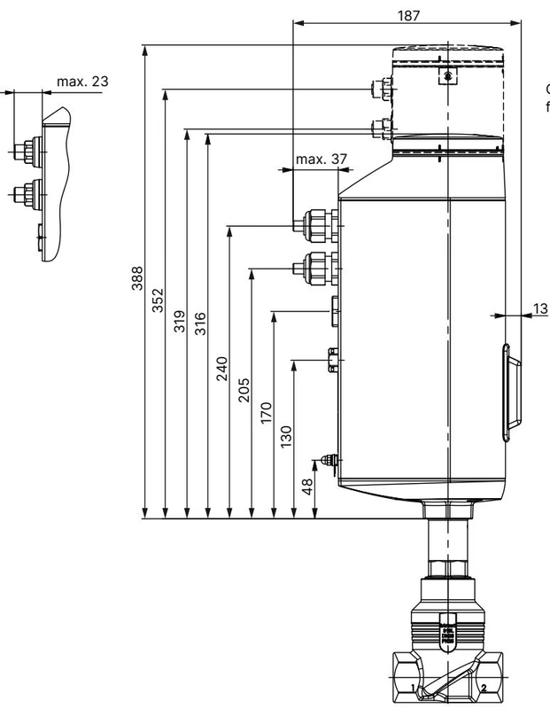
| No. | Component | Material |
|---|---|---|
| 1 | Spindle | Stainless steel 1.4401 (316)/1.4404 (316L) |
| 2 | Spindle seal | PTFE V-seals (filled) with spring compensation |
| 3 | Spindle guide | Stainless steel 1.4404 (316L) |
| 4 | Packing gland tube | Stainless steel 1.4401 (316) |
| 5 | Seal valve body | Graphite or PTFE |
| 6 | Seat seal | Stainless steel 1.4571, PTFE, or PEEK seal washer |
| 7 | Control cone | Stainless steel 1.4571 (optionally hardened) |
| 8 | Valve seat | Stainless steel 1.4571 (optionally hardened) |
| 9 | O-ring valve seat | EPDM or PTFE |
| 10 | Valve body | Stainless steel CF3M |
The following dimensions apply to the body with threaded connections (G, NPT, RC). Dimensions are in mm unless otherwise stated.
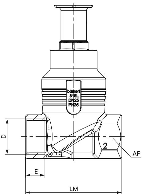
| DN | NPS | G | NPT | RC | LM | AF |
|---|---|---|---|---|---|---|
| 10 | 3/8 | 12 | 10.3 | 10.1 | 65 | 27 |
| 15 | 1/2 | 14 | 13.7 | 13.2 | 65 | 27 |
| 20 | 3/4 | 16 | 14 | 14.5 | 75 | 34 |
| 25 | 1 | 18 | 16.8 | 16.8 | 90 | 41 |
| 32 | 1 1/4 | 20 | 17.3 | 19.1 | 110 | 50 |
| 40 | 1 1/2 | 22 | 17.3 | 19.1 | 120 | 55 |
| 50 | 2 | 24 | 17.6 | 23.4 | 150 | 70 |
In addition to the maximum operating pressures, the application range of Bürkert process valves is limited by the nominal pressure in accordance with the relevant standard.
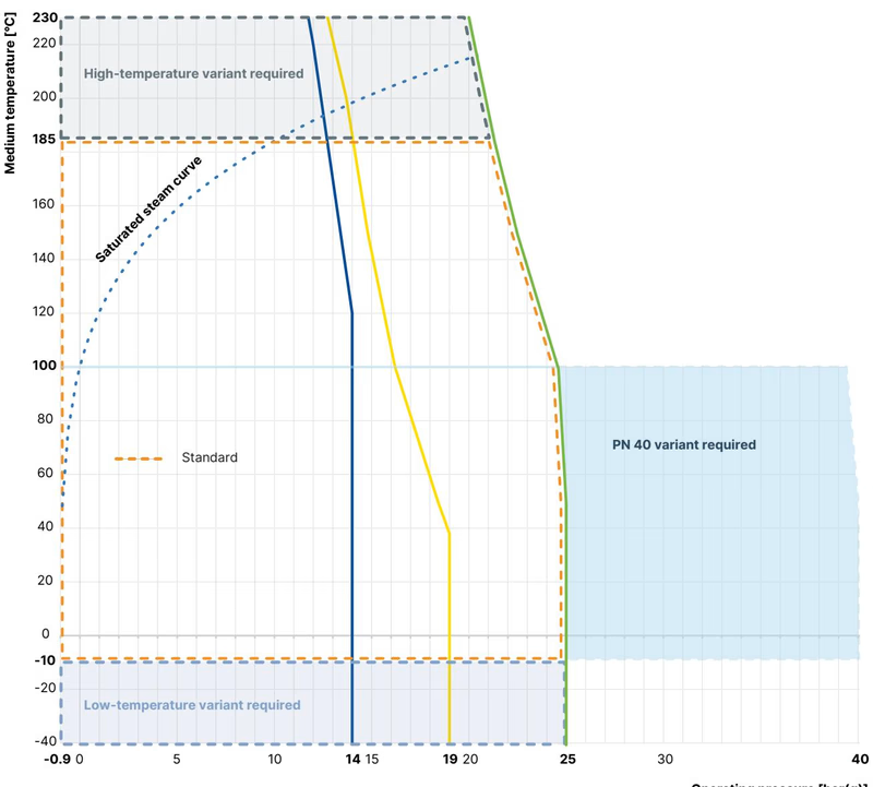
Seat Seal Selection
For tight sealing requirements, soft seals (PTFE for ≤ +130 °C, PEEK for up to +230 °C) are recommended. Metallic seals (Stainless steel) are impervious under demanding process conditions but have larger leakages (Class III/IV).
The electromotive linear drive consists of a brushless DC motor, a gear, and a spindle system that transfers the force to the closing element. The integrated electronics are controlled either by standard signals or via a fieldbus (digital).
The optional SAFEPOS energy-pack provides the actuator with the required energy to move the valve into a desired safety position in the event of a power failure.
Safety Instructions
Risk of injury from high pressure. Before working on the system or device, switch off the pressure and vent or drain lines. Perform installation and maintenance work only in the isolated state.
Explore similar products in our catalog