


Up to 99.8% Efficiency

BURKERT 20109497 (Type 3361) is an electromotive 2-way globe control valve with 2" NPT port, 24 V DC supply, 2500 N AG2 actuator, stainless steel seat, EtherNet/IP, and SAFEPOS energy storage.
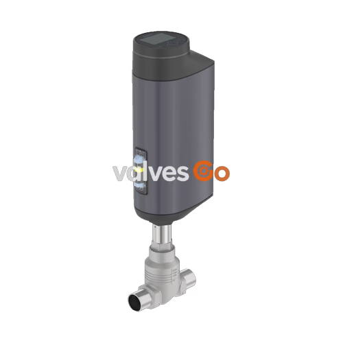
BURKERT 20109497 (Type 3361) is an electromotive two-way globe control valve engineered for high-precision, continuous fluid modulation in demanding industrial installations. The assembly pairs a CF3M cast stainless steel valve body featuring 2" NPT internal threaded ports (DN 50) with an AG2 electromotive linear actuator that produces 2500 N of positioning force. Actuated via a precision ball screw drive operating at 4 mm/s, the device eliminates mechanical backlash and isolates the valve position from line pressure transients or upstream hydraulic shocks. A 50 mm orifice with a metallic 1.4571 stainless steel seat provides an equal percentage 50:1 flow characteristic with a rated flow coefficient (Kvs) of 37 m³/h (Cv 42.8 gpm).
Operating on 24 V DC (±10%), this unit incorporates an integrated digital positioner (dead band ±0.1%), an integrated fieldbus gateway supporting büS and EtherNet/IP communications, and a local human-machine interface with operation keys and a 360° multi-color LED status ring. Plant safety is secured through an internal SAFEPOS energy-pack capacitive energy storage module that automatically drives the valve to the closed position (Normally Closed) upon power loss. With IP65/IP67 and NEMA 4X environmental protection, Ecolab detergent resistance, and EC Regulation 1935/2004 food contact compliance, BURKERT 20109497 operates in demanding hygienic and utility fluid networks without requiring external control cabinets.
| Specification Parameter | Value / Detail |
|---|---|
| Valve Type | 2-way globe control valve (Type 3361) |
| Article Number (MPN) | 20109497 |
| Nominal Diameter (Port) | DN 50 (NPS 2) |
| Fluid Connection | 2" NPT internal thread (ASME B1.20.1) |
| Seat Diameter | 50 mm |
| Flow Direction | Against closing direction (below seat, 2 → 1) |
| Operating Pressure Range | 0.00 to 10.00 bar(g) |
| Nominal Pressure Rating | PN 25 (DIN EN 1333), Class 150 (DIN EN 1759) |
| Flow Coefficient (Kvs) | 37 m³/h (water at +20 °C) / Cv 42.8 gpm |
| Theoretical Rangeability | 50:1 (equal percentage curve per DIN EN 60534-2-4) |
| Seat Leakage Class | Class III and Class IV (DIN EN 60534-4) |
| Actuator Size & Driving Force | AG2 (2500 N motor force) |
| Positioning Speed | 4 mm/s (typical closing time 6.6 s) |
| Control Function | Positioner (control unit: serial via fieldbus) |
| Dead Band | ±0.1% |
| Power Supply | 24 V DC ±10% (max. residual ripple 10%) |
| Current Consumption | AG2: max. 3 A (full load incl. 1 A SAFEPOS charging); +2 A at min. temp |
| Standby Power | 2 to 5 W |
| Duty Cycle | 100% continuous |
| Fail-Safe Energy Storage | SAFEPOS energy-pack (factory delivery: Normally Closed) |
| Communication Interfaces | büS (CANopen based) + EtherNet/IP (integrated dual M12 switch) |
| Medium Temperature | -10 °C to +185 °C |
| Ambient Temperature | -25 °C to +65 °C (without modules); derated with gateway/SAFEPOS |
| Fluid Viscosity Limit | Up to 600 mm²/s |
| Enclosure Rating | IP65 / IP67 (DIN EN 60529), NEMA 4X |
| Protection Class | Class III (DIN EN 61140) |
| Food Contact Compliance | EC Regulation 1935/2004 (manufacturer declaration) |
| Cleaning Agent Resistance | Ecolab certified (F&E/P3-E No. 40-1) |
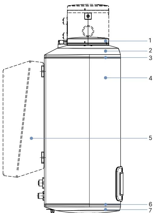
| Item | Component | Material |
|---|---|---|
| 1 | Display housing / Blind cover / Gateway housing | PPS (standard), Stainless steel 1.4301 (ATEX/IECEx) |
| 2 | Actuator cover | PPS |
| 3 | Seal | EPDM |
| 4 | Actuator housing | Powder-coated cast aluminium |
| 6 | Seal | EPDM |
| 7 | Actuator base | PPS |
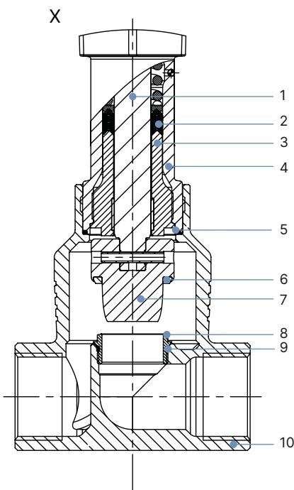
| Item | Component | Material |
|---|---|---|
| 1 | Spindle | Stainless steel 1.4401 (316) / 1.4404 (316L) |
| 2 | Spindle seal | Filled PTFE V-rings with spring compensation |
| 3 | Spindle guide | Stainless steel 1.4404 (316L) |
| 4 | Packing gland tube | Stainless steel 1.4401 (316) |
| 5 | Valve body seal | Graphite or PTFE |
| 6 | Seat seal | Stainless steel 1.4571 (optionally hardened) |
| 7 | Control cone | Stainless steel 1.4571 (optionally hardened) |
| 8 | Valve seat | Stainless steel 1.4571 (optionally hardened) |
| 9 | O-ring valve seat | EPDM or PTFE |
| 10 | Valve body | Cast stainless steel CF3M (equivalent to 316L) |
Flow passes below the seat (port 2 to port 1), countering the closing direction of the spindle to eliminate water hammer and ensure smooth opening characteristics. For seat size 50 with an AG2 2500 N drive, the maximum operating pressure is limited to 10 bar(g) in combination with metallic stainless steel seat sealing (DIN EN 60534-4 Leakage Class III/IV).
| Stroke (%) | Kv Value (m³/h) | Stroke (%) | Kv Value (m³/h) |
|---|---|---|---|
| 5% | 0.90 | 60% | 10.5 |
| 10% | 1.1 | 70% | 15.5 |
| 20% | 1.9 | 80% | 22.0 |
| 30% | 2.9 | 90% | 29.5 |
| 40% | 4.5 | 100% (Kvs) | 37.0 |
| 50% | 6.8 | Theoretical Rangeability | 50:1 |
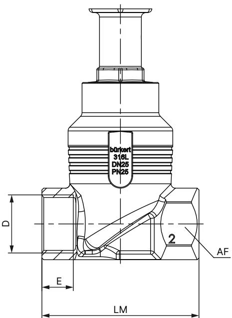
| Nominal Diameter DN | NPS | Thread Standard | Thread Depth E (mm) | Face-to-Face Length LM (mm) | Wrench Flat AF (mm) |
|---|---|---|---|---|---|
| 50 | 2 | NPT (ASME B1.20.1) | 17.6 | 150 | 70 |
| Actuator Size | Nominal Diameter | Standard Height H1 (mm) | Fieldbus Gateway Height H2 (mm) | Note |
|---|---|---|---|---|
| AG2 | DN 50 (NPS 2) | 485 | 557 | In closed position without sealing force, height increases approx. 2 mm |
INFO
The valve can be mounted in any installation orientation. An upright vertical orientation with the actuator on top is recommended to facilitate clean draining and display visibility.
BURKERT 20109497 is equipped with an integrated fieldbus gateway supporting EtherNet/IP and büS protocols. Electrical connection is implemented via industrial M12 connectors.
| Pin | Signal Assignment |
|---|---|
| 1 | CAN Shield / Protective Shield |
| 2 | Operating voltage 24 V DC ±10% |
| 3 | GND / CAN_GND |
| 4 | CAN_H |
| 5 | CAN_L |
| Pin | Signal Assignment |
|---|---|
| 1 | Transmit + (Tx+) |
| 2 | Receive + (Rx+) |
| 3 | Transmit - (Tx-) |
| 4 | Receive - (Rx-) |
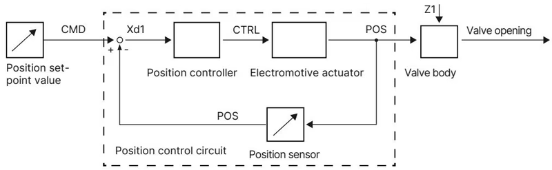
Position control operates as an internal closed control loop. A contactless displacement transducer continuously reads the spindle position (POS) and compares it with the target command value (CMD) received cyclically via EtherNet/IP or standard signal. If a system deviation (Xd1) occurs, the electronics drive the brushless motor and ball screw mechanism via actuating variable CTRL until equilibrium is reached.
The actuator cover incorporates a high-contrast display module with touch buttons. Operators can navigate through configuration menus, monitor real-time valve position and process parameters, or toggle between AUTOMATIC and MANUAL operating states directly at the device. A 360° LED light ring provides plant-floor status indication (running, warning, fault, or end-position status).
The internal SAFEPOS energy-pack capacitive energy storage module charges completely within 120 seconds of 24 V DC application. Upon a sudden power interruption, the module automatically powers the motor to drive the valve into its pre-programmed safety position (Normally Closed). Device firmware monitors the internal energy storage capacity and generates predictive maintenance alerts as capacitor wear approaches end-of-life limits (up to 10 years operational life).
Manual Override and De-energized State
The mechanical manual override and fieldbus gateway assembly must be operated or disassembled strictly in a de-energized state. When rotating the 3 mm Allen key, apply gentle axial pressure and never exceed the maximum tightening torque of 2 Nm. Exceeding 2 Nm will damage the internal manual override mechanism.
The screwed-in valve seat design allows in-line replacement or orifice resizing without replacing the valve body.
| Component Connection | Nominal Size | Tool / Socket | Required Tightening Torque |
|---|---|---|---|
| Valve Body to Actuator Connection | DN 50 (2" NPT) | Open-end wrench on body connection flat | 70 ±3 Nm |
| Screwed-in Valve Seat Installation | Seat Size 50 | Dedicated seat installation tool (Art. 652609) | 120 +8 Nm |
| Actuator Housing Fastening Screws | AG2 Actuator Cover | Torx T25 | 5.0 Nm |
| Fieldbus Gateway Fastening Screw | Gateway Module | 3 mm Hex socket screw | 1.1 Nm |
| SAFEPOS Locking Screw | Energy Storage Bracket | Torx T10 | 1.1 Nm |
Lubrication and Clean Installation
Always grease the external threads of the valve seat and body connection with an approved lubricant (e.g., Klüberpaste UH1 96-402) prior to assembly. Replace the graphite body seal ring whenever the actuator is removed from the valve body.
Calibration Requirement — X.TUNE
After replacing the valve body, seat, or control cone, run the X.TUNE self-calibration routine to recalibrate the physical stroke and closed position of the valve. The X.TUNE procedure can be triggered via the display menu, the Bürkert Communicator software, or by holding the OPEN and CLOSE internal buttons simultaneously for 5 seconds. Never execute X.TUNE while the valve is under medium pressure, as process line pressure prevents accurate physical seat zero-point detection.
Explore similar products in our catalog


