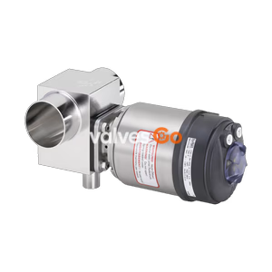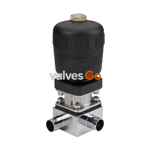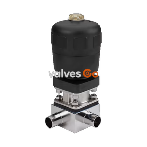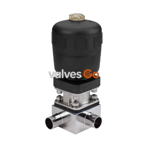
Type 2032

BURKERT 20135668 Type 2933 is a manual 2/2-way diaphragm shut-off valve with DN 50 DIN 32676-B clamp ends, 1.4435 BN2 tube body, GYLON/EPDM seal, 110 mm PPS handwheel, and 0-10 bar operating pressure.
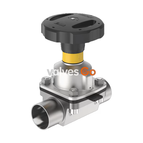
BURKERT 20135668 (Type 2933) is a manually operated 2/2-way diaphragm valve designed for shut-off applications in hygienic, aseptic, and aggressive fluid handling processes. Configured with a nominal diameter of DN 50 (NPS 2) and diaphragm size 50, this unit features a fabricated tube valve body (VP) in 316L stainless steel (1.4435-BN2) and sanitary clamp connections compliant with DIN 32676 Series B (ISO 4200 pipe). The sealing diaphragm consists of a chemically resistant GYLON® laminate with an EPDM elastomer backing, offering high integrity under continuous operating pressures from 0 to 10 bar (PN 10) and medium temperatures between -5 °C and +130 °C. The valve provides full CIP and SIP capability, supporting steam sterilisation up to +140 °C for 60 minutes. Actuation is performed manually via a 110 mm diameter PPS handwheel mounted on a stainless steel diaphragm bonnet, incorporating an integrated optical position indicator with stroke scale and an adjustable single minimum-stroke closing limiter.
BURKERT Type 2933 utilizes a flow-optimized 2-way valve body with zero dead leg to provide high flow coefficients while preventing media stagnation. The manual actuator transmits thrust via an internal spindle mechanism: turning the handwheel counterclockwise lifts the compressor to open the line, while clockwise rotation depresses the diaphragm against the body weir to close flow.
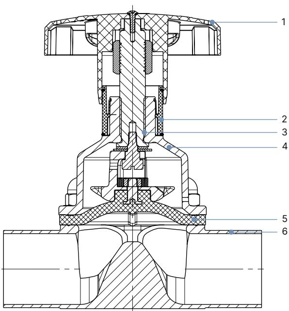
| Item | Component | Material Specification |
|---|---|---|
| 1 | Handwheel | Polyphenylene sulphide (PPS), ∅ 110 mm |
| 2 | Visual position indicator | Polyamide (PA) / Stainless steel 1.4305 |
| 3 | Valve spindle | Stainless steel 1.4305 |
| 4 | Diaphragm bonnet | Stainless steel 1.4308 |
| 5 | Diaphragm | GYLON® laminated with EPDM backing (ER code) |
| 6 | Valve body | Stainless steel tube 1.4435-BN2 / UNS S31603 (316L) |
Actuator Protection and Autoclavability
The actuator assembly features a compact, autoclavable design rated for ambient temperatures up to +130 °C (short periods up to +150 °C). The bonnet includes built-in relief bores configured to vent any leakage immediately if diaphragm integrity is compromised.
| Specification Parameter | Technical Value |
|---|---|
| Fluidic port connection quantity | 2 |
| Switch positions | 2 (shut-off valve) |
| Nominal port size | DN 50 (NPS 2) |
| Diaphragm size | 50 |
| Body port configuration | Tube valve body (VP) with clamp connection |
| Port connection standard | DIN 32676 Series B (ISO pipe ISO 4200) |
| Pipe dimensions / Clamp outer diameter | 60.3 x 2.0 mm / Clamp ∅ 77.5 mm (Product key TC47) |
| Pressure rating | 0 bar to 10 bar (PN 10 / Class 150) |
| Medium temperature range | -5 °C to +130 °C |
| Steam sterilisation limit | Up to +140 °C for max. 60 minutes |
| Ambient operating temperature | -10 °C to +130 °C (temporary +150 °C) |
| Flow coefficient Kv (water, Δp = 1 bar) | 70 m³/h (Cv 81.6 gal/min; VP nominal water curve: 69.7 m³/h) |
| Handwheel dimensions | ∅ 110 mm (Medium designation M) |
| Spindle lead / slope per rotation | 2.0 mm |
| CIP / SIP capability | Yes |
| Product identification | Data matrix code on product label |
Actuator dimensions and body layout conform to standardized hygienic dimensional standards. For diaphragm size 50, manual actuator dimensions are summarized below.
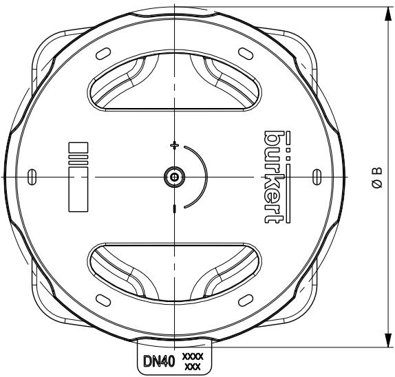
| Diaphragm Size | Handwheel Designation | H1 (Open) [mm] | H2 (Closed) [mm] | Handwheel ∅ B [mm] |
|---|---|---|---|---|
| 32 | M | 129 | 115 | 110 |
| 40 | M | 134 | 116 | 110 |
| 50 | M | 149 | 125 | 110 |
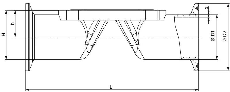
| Diaphragm Size | Port DN | ∅D1 [mm] | s [mm] | ∅D2 [mm] | L [mm] | h [mm] | H [mm] | Product Key |
|---|---|---|---|---|---|---|---|---|
| 8 | 8 | 13.5 | 1.6 | 25.0 | 89 | 9.85 | 22.35 | TC40 |
| 8 | 10 | 17.2 | 1.6 | 25.0 | 89 | 11.70 | 24.20 | TC53 |
| 15 | 15 | 21.3 | 1.6 | 50.5 | 110 | 14.35 | 39.60 | TC52 |
| 20 | 20 | 26.9 | 1.6 | 50.5 | 119 | 17.15 | 42.40 | TC43 |
| 25 | 25 | 33.7 | 2.0 | 50.5 | 129 | 20.55 | 45.80 | TC44 |
| 32 | 32 | 42.4 | 2.0 | 64.0 | 148 | 25.10 | 57.10 | TC55 |
| 40 | 40 | 48.3 | 2.0 | 64.0 | 161 | 29.35 | 61.35 | TC46 |
| 50 | 50 | 60.3 | 2.0 | 77.5 | 192 | 35.35 | 74.10 | TC47 |
Actuators for diaphragm sizes 15 to 50 are equipped with a high-visibility yellow optical position indicator and marked stroke scale. As the handwheel is turned counterclockwise, the yellow indicator emerges from beneath the handwheel collar.
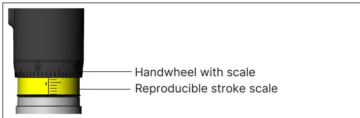
Type 2933 incorporates an adjustable minimum stroke limiter that protects the GYLON®/EPDM diaphragm from excessive compressive strain.
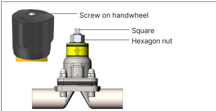
Stroke Limiter Operating Limits
Do not screw the hexagon nut onto the square portion of the spindle. The minimum stroke limit adjustment is strictly intended for the 0% to 25% opening stroke range.
Type 2933 can be mounted in any orientation, although positioning the actuator vertically upward is preferred.
Operating Closure Force
Tighten the handwheel only until tactile shut-off resistance is achieved. Applying excessive manual torque damages the diaphragm and accelerates fatigue without improving seal integrity.
Assembly screws must be torqued evenly in a crosswise pattern in 3 successive stages (approximately 1/3, 2/3, and full torque).
| Diaphragm Size | Cast / Forged / Plastic Bodies [Nm] | Tube Valve Body (VP) [Nm] |
|---|---|---|
| 8 | 2.5 | 2.5 |
| 15 | 4 | 4 |
| 20 | 4.5 | 4.5 |
| 25 | 6 | 8 |
| 32 | 8 | 10 |
| 40 | 10 | 15 |
| 50 (GYLON® / PTFE) | 15 | 20 |
| 65 | 30 | 30 |
| 80 | 40 | 40 |
| 100 | 40 | — |
A torque tolerance of +10% applies to all specified values.
The manual actuator requires no lubrication or periodic internal overhaul under normal operation. The diaphragm should be examined at intervals not exceeding 100,000 switching cycles, or sooner when conveying abrasive slurries.
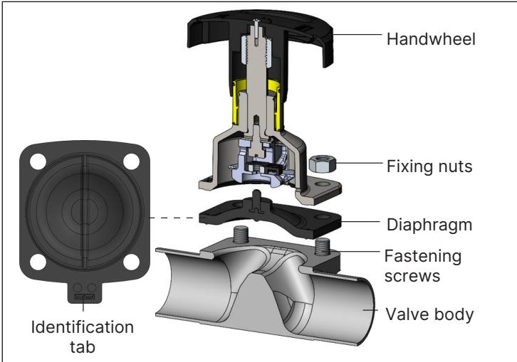
| Diaphragm Size | Diaphragm Material | Bürkert Material Code | Fastening Type | Article Number |
|---|---|---|---|---|
| 50 | GYLON® laminated with EPDM (ER) | PTFE L08 | Threaded connection | 693 181 |
| Accessory Description | Article Number |
|---|---|
| 4-fold nylon locking mechanism with 3 mm bracket | 93719475 |
| Inductive proximity switch (initiator) M5 | 550412 |
| Inductive proximity switch (initiator) M5 ATEX | 904779 |
| Inductive proximity switch (initiator) M8 | 902475 |
| Inductive proximity switch (initiator) M12 | 902473 |
Feedback for upper or lower travel limits can be installed if the diaphragm bonnet is ordered with dual M5 x 0.5 threaded sensor ports. Proximity switches sense compressor travel directly rather than the diaphragm sealing face.
BURKERT 20135668 complies with relevant European harmonisation directives and hygienic standards:
Explore similar products in our catalog