Type 2032

Burkert Type 2933 (Model 20149357) 2/2-way manual diaphragm valve. Features DN 20 welded connection, stainless steel tube body, EPDM diaphragm, and PPS handwheel.
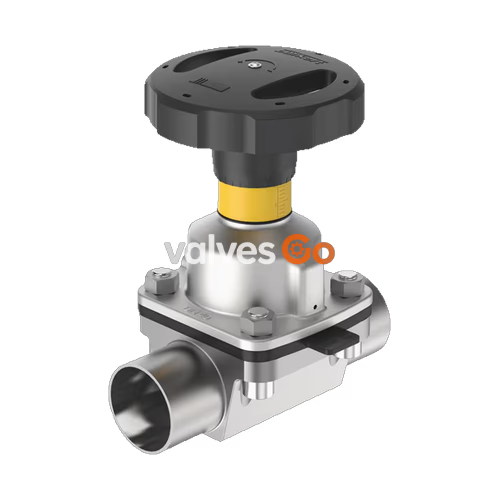
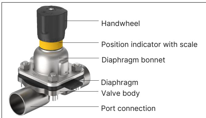
BURKERT 20149357 (Type 2933) is a 2/2-way manual diaphragm valve designed for reliable on/off control in demanding environments. This specific model features a DN 20 (NPS 3/4) welded connection, a flow-optimized stainless steel tube valve body (VP), and a high-temperature EPDM diaphragm. The manual actuator is equipped with a PPS handwheel, making it suitable for hygienic or aggressive ambient conditions. It is rated for a nominal pressure of 0 to 10 bar and can handle medium temperatures from -10 °C to 143 °C, including steam sterilization up to 150 °C for 60 minutes.
The actuator has a compact, autoclavable design and includes an integrated visual position indicator, a reproducible stroke scale, and an adjustable closing limiter to protect the diaphragm from excessive force. The valve is FDA and USP Class VI compliant, ensuring its suitability for food, beverage, and pharmaceutical applications.
Explosion Protection
An explosion-proof ATEX/IECEx device variant is available. When used in potentially explosive atmospheres, ensure the device is properly grounded and observe all safety instructions regarding electrostatic charging.
| No. | Element | Material |
|---|---|---|
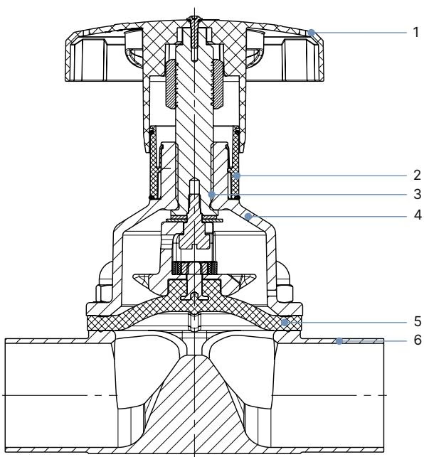
| 1 | Handwheel | Polyphenylene sulphide (PPS) |
| 2 | Visual position indicator | Polyamide (PA), Stainless steel 1.4305 |
| 3 | Valve spindle | Stainless steel 1.4305 |
| 4 | Diaphragm bonnet | Stainless steel 1.4308, polyphenylene sulphide (PPS) |
| 5 | Diaphragm | EPDM high-temperature |
| 6 | Valve body | Stainless Steel Tube 316L/1.4435 BN2 |
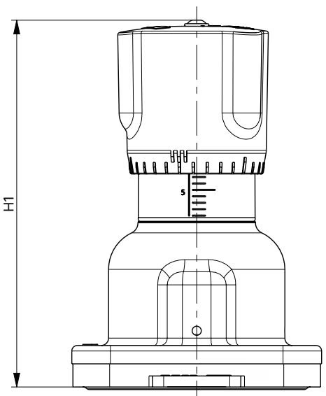
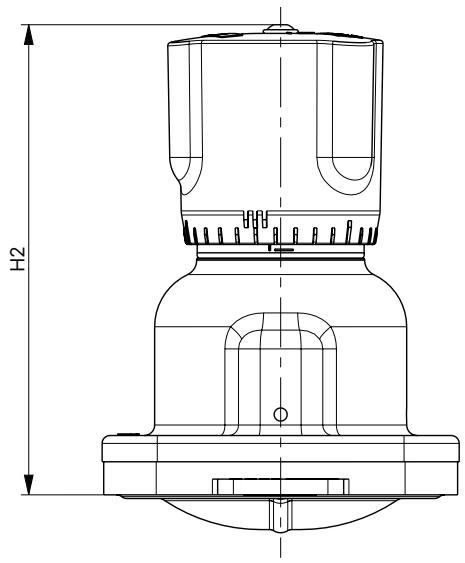
| Position open | Position closed |
|---|---|
 |  |
| Diaphragm size | H1 | H2 | ∅ B |
|---|---|---|---|
| 15 | 84 mm | 78 mm | 45 mm |
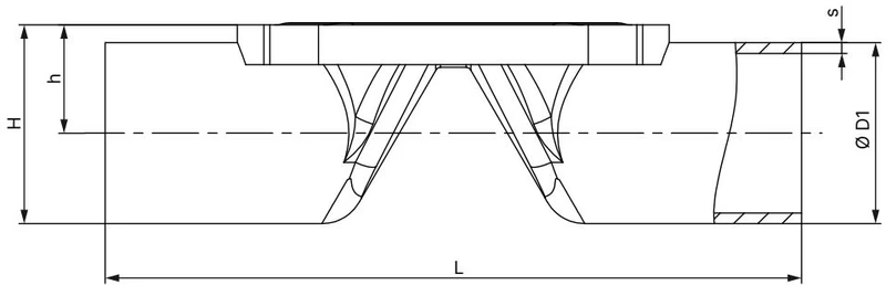
ASME BPE / DIN 11866 Series C
| Diaphragm size | Port connection Inch | ∅D1 | s | L | h | H |
|---|---|---|---|---|---|---|
| 15 | 3/4" | 19.05 | 1.65 | 117 | 13.23 | 25.73 |
WARNING
The following tightening torques refer to the static media pressures specified. Excessive torque can shorten the service life of the diaphragm.
| Diaphragm size | Maximum static operating pressure [bar] | Tightening torque (Static) [Nm] | Tightening torque (Dynamic) [Nm] |
|---|---|---|---|
| 15 | 10 | 0.8 | 1.5 |
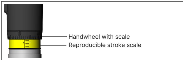
Turning the handwheel counterclockwise reveals the yellow position indicator and the scale marked on it as the valve opens further. The stroke scale shows the relative position of the valve and serves as a fixation point for determining the rotation position.
It is the responsibility of the installer and the operator to ensure self-draining. The angle of inclination should correspond to the angle of inclination of the pipeline. The marking on the port connection of the valve body serves as an orientation aid and must point upwards.
This model is fitted with a minimum stroke limiter which also serves as a closing limiter to protect the diaphragm.
TIP
Only tighten the device by hand when closing it, and do not use any tools or aids. Too much tightening may damage the device.
Explore similar products in our catalog