


Up to 99.8% Efficiency

Burkert 328407 (Type 2301) is a pneumatically operated 2-way globe control valve with G 1/2 threaded ports, DN 15 orifice, stainless steel body and seat, Kvs 3.1 m³/h, and normally closed control function A.
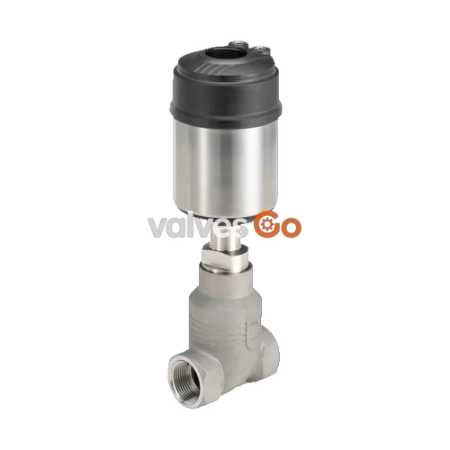
BURKERT 328407 (Type 2301) is a pneumatically operated 2-way globe control valve engineered for continuous fluid control in demanding industrial and hygienic process environments. Built on the ELEMENT platform, this unit integrates a DN 15 cast stainless steel 316L / CF3M body with G 1/2 female threaded ports, a 10 mm seat diameter, and an equal-percentage parabolic control cone delivering a flow coefficient ($K_{vs}$) of 3.1 m³/h. Operating under control function A (normally closed by spring force), the valve directs process media below the seat to ensure closing against flow while maintaining a theoretical rangeability of 50:1 and leakage class IV sealing integrity per DIN EN 60534-4.

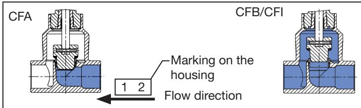
Process media enters the valve body below the seat and flows upward against the parabolic plug. Closing against the flow path eliminates water hammer effects in liquid lines and improves low-stroke throttling stability. For control function A, integrated springs inside the pneumatic actuator maintain the closed rest position; pilot air applied to the lower chamber lifts the spindle and opens the flow path.
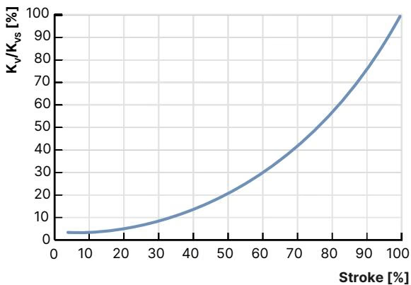
The parabolic contour on the stainless steel 1.4571 control cone provides an equal-percentage characteristic per DIN EN 60534-2-4. Across a theoretical rangeability of 50:1, the effective flow coefficient scales with valve stroke as documented below:
| Stroke Percentage | 10% | 20% | 30% | 40% | 50% | 60% | 70% | 80% | 90% | 100% ($K_{vs}$) |
|---|---|---|---|---|---|---|---|---|---|---|
| $K_v$ Value Water [m³/h] | 0.11 | 0.15 | 0.19 | 0.31 | 0.49 | 0.75 | 1.10 | 1.70 | 2.50 | 3.10 |
Actuator Sizing Advantage
Actuator size ∅ 70 mm (Size M) provides higher positioning stiffness and superior control precision compared to smaller ∅ 50 mm actuators, fulfilling tight $K_{VR}$ tilt tolerances at 5% to 10% stroke thresholds.
Type 2301 ELEMENT valves feature wetted parts in high-grade stainless steel with spring-compensated spindle packings to ensure high cycle life and external tightness.
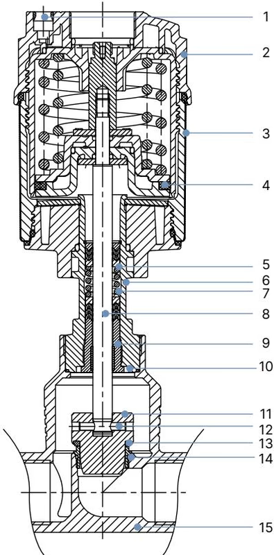
| Position | Element | Material |
|---|---|---|
| 1 | Pilot air ports | Push-in connector PP (for 6 mm hose) |
| 2 | Actuator cover | PPS (polyphenylene sulphide) |
| 3 | Actuator casing | Stainless steel 1.4561 (316Ti) |
| 4 | Piston seal | FKM |
| 5 | Springs | Stainless steel 1.4310 |
| 6 | Pipe / distance tube | Stainless steel CF3M |
| 7 | Packing gland | Filled PTFE V-rings, spring-compensated |
| 8 | Spindle | Stainless steel 1.4401 (316) / 1.4404 (316L) |
| 9 | Spindle guide | Stainless steel 1.4404 (316L), PTFE filled |
| 10 | Body seal | Graphite or PTFE |
| 11 | Control cone | Stainless steel 1.4571 |
| 12 | Spring straight pin | Stainless steel 1.4310 |
| 13 | Seat seal | Stainless steel 1.4571 (Seat leakage Class IV) |
| 14 | Valve seat with O-ring | Stainless steel 1.4571, EPDM |
| 15 | Valve body | Stainless steel 316L / CF3M |
Body and actuator dimensions for article number 328407 correspond to the DN 15 female threaded body with actuator size 70 mm (M).
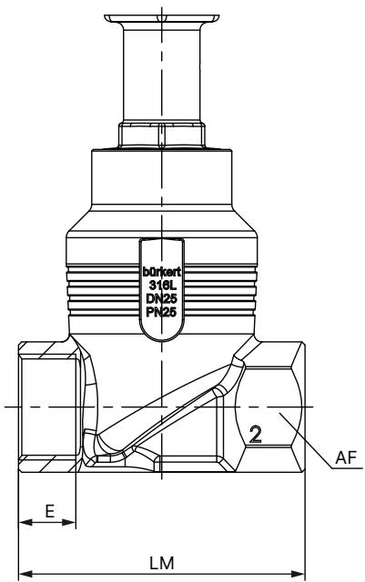
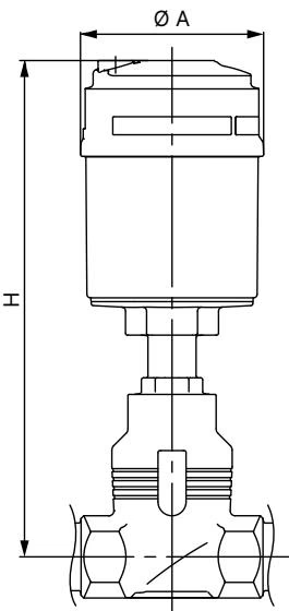
| Connection Standard | Port Size | DN | Thread Depth E [mm] | Body Length LM [mm] | Wrench Flat AF [mm] |
|---|---|---|---|---|---|
| G female (DIN ISO 228-1) | G 1/2 | DN 15 | 14.0 | 65.0 | 27.0 |
| Actuator Size | Actuator Diameter ∅ A [mm] | Base Height H [mm] | HS with Type 8692 / 8693 [mm] | HS with Type 8694 / 8696 [mm] | HS with Type 8792 / 8793 [mm] |
|---|---|---|---|---|---|
| 70 mm (M) | 91.0 | 239.0 | 383.0 | 342.0 | 342.0 |
Operating pressures must remain within the boundary conditions determined by the nominal pressure rating, fluid temperature, and connection type. For DIN EN 12516-1 / PN 25 valve bodies, permissible medium pressure decreases at elevated temperatures as follows:
| Medium Temperature [°C] | -10 to +50 °C | +100 °C | +150 °C | +200 °C | +230 °C |
|---|---|---|---|---|---|
| Maximum Medium Pressure [bar(g)] | 25.0 | 24.5 | 22.4 | 20.3 | 19.0 |
For article 328407, the maximum operating pressure across the specified range is 16 bar(g). The valve is fully vacuum tight down to -0.9 bar(g) and accommodates steam sterilisation (SIP) cycles.
| Parameter | Boundary Condition | Value |
|---|---|---|
| Seat leakage class | DIN EN 60534-4 | Class IV (metallic seal, ≤ 0.01% $K_{vs}$) |
| Fluid media | Industrial liquids, gases, steam | Water, neutral gases, steam, alcohols, oils, organic solvents |
| Medium temperature range | Standard continuous | -10 °C to +185 °C |
| Ambient temperature range | Standalone actuator | -10 °C to +100 °C |
| Ambient with positioner | Type 8692 / 8693 / 8694 | -10 °C to +55 °C |
| Ambient with remote sensor | Type 8798 / 8792 / 8793 | -10 °C to +80 °C |
| Pilot control pressure | Control function A | 5.5 bar(g) to 7.0 bar(g) (10 bar max without positioner) |
| Pilot air quality | DIN ISO 8573-1 | Class 3 (moisture), Class 5 (dust and oil) |
Article 328407 integrates directly with Burkert digital positioners and process controllers via an internal air duct system without external tubing:
Tubing-Free Control Top Installation
Mounting a Type 8692/8693/8694 control top directly onto the actuator interface routes pilot air internally through integrated seal plugs, eliminating external pneumatic hoses and reducing leak points.
Observe technical rules and safety instructions during line preparation and mounting:
Prevent Seal Contour Damage
Never rotate the actuator or disassemble the drive assembly while the valve is in the closed position. Always apply 5 bar pilot pressure to open the valve prior to rotating or unscrewing the actuator.
Conduct regular visual inspections at least once annually. Under heavy cycling or high medium temperatures, shorten inspection intervals accordingly.
Explore similar products in our catalog


