


Up to 99.8% Efficiency

BURKERT 329186 (Type 3280) is an electromotive 2-way globe control valve with NPT 3/8" brass body, 6 mm orifice, EPDM seal, 0.9 m3/h Kv, 24 V DC supply, 0-10 V analog input, and IP54 rating.
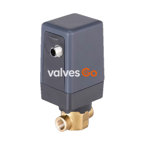
BURKERT Type 3280 (item 329186) is a direct-acting electromotive 2-way globe control valve designed for dosing neutral liquid and gaseous media in closed or open control loops. Driven by a linear stepper motor coupled to a threaded spindle, the valve delivers continuous throttling with a closing time of approximately 2.5 seconds. Integrated control electronics handle position regulation directly from an external analogue signal without requiring external driver modules. In stationary holding positions, the motor is switched off, reducing continuous electrical power consumption to below 1 W.
This specific configuration incorporates a brass valve body with internal NPT 3/8" threaded ports, a 6 mm seat orifice (DN 6), and an EPDM elastomer seat and stem seal. Operating within a fluid pressure range of 0 to 6 bar(g), it achieves a nominal flow coefficient Kv of 0.9 m³/h with flow directed underneath the valve seat.
| Specification Parameter | Value / Range |
|---|---|
| Valve Type / Article Number | Type 3280 / 329186 |
| Control Function | Standard control valve (Version H, continuous positioning) |
| Port Connection | NPT 3/8" female thread (ASME B1.20.1) |
| Seat Orifice Diameter | 6 mm (1/4") |
| Flow Rate Kv Value (Water) | 0.9 m³/h |
| Operating Pressure Range | 0 to 6 bar(g) |
| Supply Voltage | 24 V DC ±10% (max. residual ripple 10%) |
| Power Consumption | < 1 W holding mode; max. 8 W operating (DN 2 to DN 6) |
| Actuating Time (0 to 100%) | Approx. 2.5 s (normal speed) / 5 s (slow speed) |
| Analogue Set-Point Input | 0 to 10 V (default, 22 kΩ input impedance); selectable 4 to 20 mA (60 Ω) |
| Digital Output Feedback | PNP, max. 100 mA current limit (active when valve closed) |
| Dead Band of Position Control | ±0.5% (relative to full stroke range, setting range 1:100) |
| Medium Temperature | 0 °C to +70 °C (EPDM material limits: -30 °C to +70 °C) |
| Ambient Temperature | -10 °C to +60 °C (subject to motor duty cycle derating) |
| Flow Direction | Under seat (flow against closing direction) |
| Maximum Viscosity | 600 mm²/s (cSt) |
| Enclosure Rating | IP54 (with mated M12 connection cable) |
| Weight | Approx. 0.7 kg |
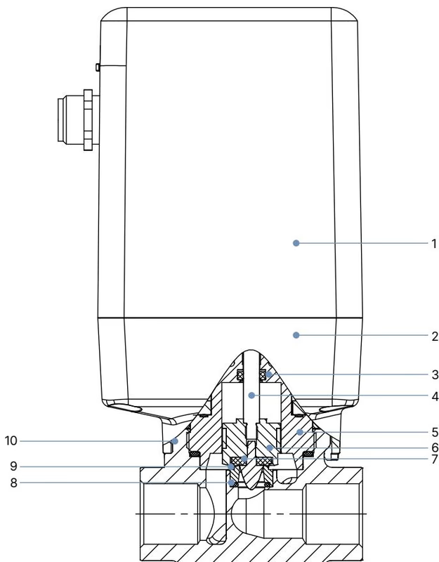
The Type 3280 actuator is completely isolated from the process fluid. Translational movement generated by the stepper motor threaded spindle drives the rigid valve spindle connected to a parabolic control element. The guiding shaft and piston maintain precise alignment during repeated cycling.
| Item | Component | Material |
|---|---|---|
| 1 | Housing Cover | Polycarbonate (PC GF10) |
| 2 | Housing Base | Polyphenylene sulfide (PPS GF40) |
| 3 | Spindle Seal | EPDM (Ethylene-propylene-diene rubber) |
| 4 | Spindle | Stainless steel 1.4305 |
| 5 | Upper Valve Body | Brass |
| 6 | Piston with Parabolic Control Element | PTFE and Stainless steel 1.4305 |
| 7 | Elastomer Seat Seal | EPDM |
| 8 | O-Ring | EPDM |
| 9 | Seat Ring | Stainless steel 1.4301 / 1.4305 |
| 10 | Valve Body | Brass |
INFO
All wetted materials in contact with the operating fluid conform to the Code of Federal Regulations published by the FDA according to the manufacturer declaration.
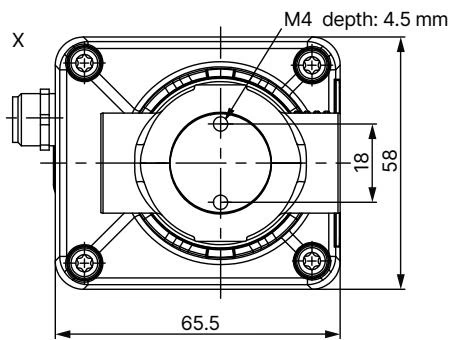
Dimensions for threaded body variants of Type 3280 (all dimensions in mm):
| Port Thread D | A | B | C | E | F | G | H |
|---|---|---|---|---|---|---|---|
| NPT 3/8" (329186) | 6.0 | 10.3 | — | 97.4 | 137.2 | 12.0 | 27.5 |
| G 3/8" | — | — | 12.0 | 97.4 | 137.2 | 12.0 | 27.5 |
| NPT 1/4" | 5.8 | 10.0 | — | 96.4 | 134.2 | 10.0 | 27.5 |
| G 1/4" | — | — | 12.0 | 96.4 | 134.2 | 10.0 | 27.5 |
| NPT 1/2" | 8.2 | 13.7 | — | 97.4 | 139.2 | 14.0 | 29.5 |
| G 1/2" | — | — | 14.0 | 97.4 | 139.2 | 14.0 | 29.5 |
Actuator housing mounting threads: 4× M4 female threads, depth 4.5 mm, spaced at pitch centres of 27.5 mm.
Electrical connection is established via an 8-pin M12 A-coded circular connector located on the side of the actuator. None of the electrical inputs and outputs are galvanically isolated from the 24 V DC supply voltage. The threaded metal sleeve of the M12 connector connects directly to the valve body for protective earth bonding.
| Pin | Wire Colour (Cable 919061) | Configuration | Function / Operating Signal |
|---|---|---|---|
| 1 | White | Supply + | 24 V DC ±10%, max. residual ripple 10% |
| 2 | Brown | Supply GND | 24 V DC ground |
| 3 | Green | Do not connect | Electrically insulate wire on connection line |
| 4 | Yellow | Do not connect | Electrically insulate wire on connection line |
| 5 | Grey | Do not connect | Electrically insulate wire on connection line |
| 6 | Pink | Set-point value input + | 0 to 10 V (default) / 4 to 20 mA or PWM (800 Hz) |
| 7 | Blue | Digital output | PNP, max. 100 mA (0 to 5 V = log 0; 10 to 30 V = log 1 closed) |
| 8 | Red | Signal GND | Signal reference ground |
| Body | — | Shielding | Connected to valve body / functional ground |
WARNING
Do not connect pins 3, 4, or 5 on standard control valve devices. The cable shield must be grounded via the M12 connector housing to comply with electromagnetic compatibility (EMC) requirements.
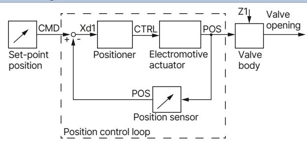
The standard control valve version converts the external analogue set-point value directly into a valve position. Status indication is handled visually through the multi-colour LED on the actuator cover. In addition, when the valve reaches its closed end position, the internal digital transistor output (Pin 7) switches to active high (10 to 30 V DC).
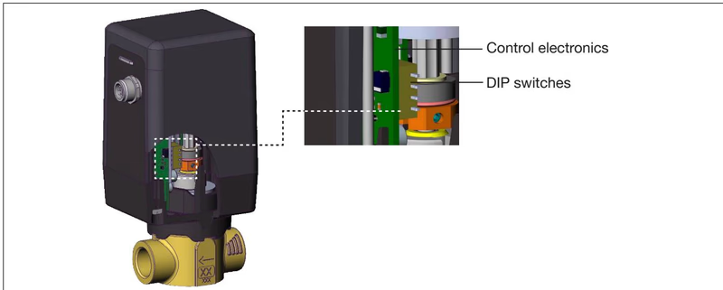
Four internal DIP switches located on the electronic PCB beneath the actuator cover permit hardware adaptation of operating parameters:
| DIP Switch | Position | Control Valve Function (Version H) |
|---|---|---|
| 1 | OFF | Normal operating direction (increasing signal opens valve, e.g. 0 to 10 V = 0 to 100% stroke) |
| ON | Inverted operating direction (decreasing signal opens valve, e.g. 10 to 0 V = 0 to 100% stroke) | |
| 2 | OFF | Set-point value input: 4 to 20 mA (input impedance 60 Ω) |
| ON | Set-point value input: 0 to 10 V (input impedance 22 kΩ, factory setting for 329186) | |
| 3 | OFF | Actuating speed: Normal mode (approx. 2.5 s for full stroke) |
| ON | Actuating speed: Slow mode (approx. 5.0 s for full stroke) | |
| 4 | OFF | Low power function: Off (full torque and standard operating pressure up to 6 bar) |
| ON | Low power function: On (reduced motor current and lower heat emission; max. medium pressure 3 bar, max. Δp 1 bar) |
Actuator Cover Removal and Assembly
Disconnect power before opening the 4 captive screws on the bottom side of the actuator housing. When lifting the cover, support the connection plate on the connector plug so it remains seated on the housing. When reassembling, verify that internal wiring is not pinched and tighten screws to 2 Nm.
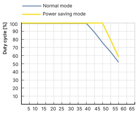
Duty cycle refers to the actual running time of the stepper motor during repositioning. High ambient temperatures increase internal motor heating. For DN 6 valves with fluid pressures up to 6 bar, continuous 100% duty cycle is permitted at ambient temperatures up to +40 °C. At +60 °C ambient, permissible motor duty cycle decreases to approximately 40%. Operating beyond recommended duty cycle limits leads to overheating and reduced operating life.
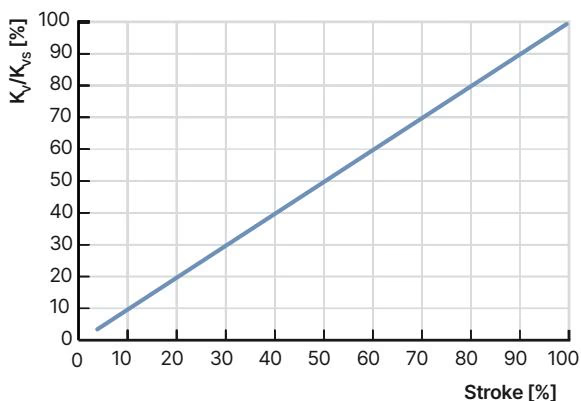
Model 329186 features a parabolic valve plug delivering a linear flow characteristic with a nominal Kv value of 0.9 m³/h at 100% stroke. To ensure responsive closed-loop control across the operating span, the pressure drop across the fully opened valve should represent at least 25% of the total system pressure drop (Δp_valve > 0.25 · Δp_total).
For fluid calculation:
To drive the valve into a predetermined safe position during a power failure, an external capacitive buffer module (Type 1573, Article no. 773440) can be placed in line with the 24 V DC power feed. In the event of mains power loss, the buffer module supplies 18 V DC for several seconds. The valve electronics detect the voltage drop and automatically drive the spindle to the closed safety position.
| Accessory Description | Article Number |
|---|---|
| Capacitive buffer module (Type 1573) for power failure safety position | 773440 |
| M12 circular socket with 2 m cable, 8-pin, unshielded | 919061 |
| M12 circular socket with 2 m cable, 8-pin, shielded | 918991 |
| Rail-mounted power supply (Type 1573), 100 to 240 V AC / 24 V DC, 1 A, NEC Class 2 | 772361 |
| Rail-mounted power supply (Type 1573), 100 to 240 V AC / 24 V DC, 2 A, NEC Class 2 | 772362 |
Under clean process fluid conditions, BURKERT Type 3280 is maintenance-free. Clean external housing parts using neutral agents; do not use alkaline cleaning solutions.
| Fault Symptom | Probable Cause | Corrective Action |
|---|---|---|
| LED off | 24 V DC supply disconnected or polarity inverted | Check power wiring at M12 pins 1 (+) and 2 (-) |
| LED flashes red | Supply voltage ripple exceeds 10% | Use regulated power supply with smooth output voltage |
| Overheating detected | Verify ambient temperature against derating curve; reduce repositioning frequency | |
| Set-point signal < 4 mA (when 4-20 mA selected) | Check analogue control loop wiring for breaks | |
| Valve does not open | Set-point value below 1% cut-off threshold | Increase set-point signal above cut-off limit |
| Valve reverses action | DIP switch 1 set incorrectly | Invert DIP switch 1 setting |
| Incomplete travel | Low power mode enabled on excessive differential pressure | Switch DIP switch 4 to OFF |
| Internal seat leakage | Debris trapped between seat and seal | Flush piping; inspect seat; install upstream dirt filter (≤ 0.3 mm) |
Explore similar products in our catalog


