


Up to 99.8% Efficiency

BURKERT 339405 (Type 3361) is an electromotive 2-way globe control valve with 24 V DC supply, DN 10 weld ends, AG2 1300 N linear actuator, SAFEPOS energy pack, stainless steel seat, and 0-25 bar rating.
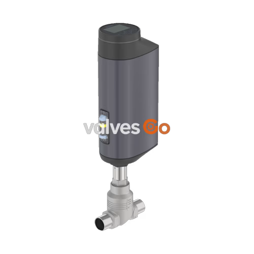
BURKERT 339405 (Type 3361) is an electromotive 2-way globe control valve engineered for continuous closed-loop control in industrial fluid handling systems. Driven by an AG2 electromotive linear actuator equipped with a brushless DC motor and precision ball screw, article 339405 delivers a positioning speed of 6 mm/s at 1,300 N nominal driving force. Operating independently of medium pressure variations, the actuator positions the control cone with a positioning dead band of ±0.1%.
Configured as article 339405, this assembly combines a DN 10 (NPS 3/8) welded stainless steel CF3M body complying with DIN EN ISO 1127 / ISO 4200 / DIN 11866 Series B with a 6 mm (1/4") nominal diameter stainless steel seat and a linear 25:1 control cone. The unit achieves a nominal water flow coefficient Kv of 1.2 m³/h (Cv 1.4 gpm) with flow directed below the seat (port 2 → 1). An integrated electrical SAFEPOS energy-pack provides emergency power to drive the valve into a fail-safe closed position upon interruption of the external 24 V DC supply.
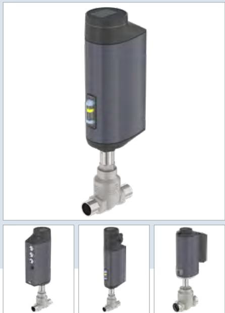
| Specification Parameter | Technical Data (Article 339405 / Type 3361 AG2) |
|---|---|
| Product Design | Electromotive 2-way globe control valve |
| Valve Article Number | 339405 |
| Valve Type Family | Type 3361 |
| Actuator Size & Driving Force | AG2 (1,300 N nominal force) |
| Travel Speed | 6 mm/s (for AG2 1,300 N) |
| Typical Closing Time | 3.4 s (total AG2 operating range 3.3 to 6.6 s) |
| Dead Band of Position Control | ±0.1% |
| Nominal Pipeline Diameter | DN 10 (NPS 3/8) |
| Pipe Interface Standard | DIN EN ISO 1127 / ISO 4200 / DIN 11866 Series B (17.2 x 1.6 mm) |
| Seat Orifice Size | 6 mm (1/4") |
| Flow Coefficient (Water) | Kv = 1.2 m³/h (Cv = 1.4 gpm) |
| Control Cone Characteristic | Linear 25:1 |
| Operating Pressure Range | 0 to 25 bar(g) (PN 25 / Class 150) |
| Medium Temperature Range | -10 °C to +185 °C |
| Ambient Temperature Range | -25 °C to +65 °C (with module derating) |
| Seat Seal Tightness | Leakage Class IV (DIN EN 60534-4) |
| Operating Supply Voltage | 24 V DC ±10% (max. residual ripple 10%) |
| Operating Current | AG2: Max. 3 A (including 1 A SAFEPOS charging current); +2 A at minimum ambient temperature |
| Standby Power Consumption | 2 to 5 W |
| Duty Cycle | 100% continuous |
| Electrical Protection Class | Class III (DIN EN 61140) |
| Ingress Protection | IP65 / IP67 (DIN EN 60529), NEMA 4X |
| Control Interface | Analogue standard signals, Service-büS, internal buttons/DIP switches (no display) |
| Food Contact Approvals | EC Regulation 1935/2004, FDA 21 CFR wetted materials conformity |
| Detergent Resistance | Certified according to Ecolab test method F&E/P3-E No. 40-1 |
Article 339405 uses an all-metal valve body paired with an aluminium and engineered plastic actuator housing. Wetted surfaces satisfy hygienic standards and resist corrosion during industrial washdowns.
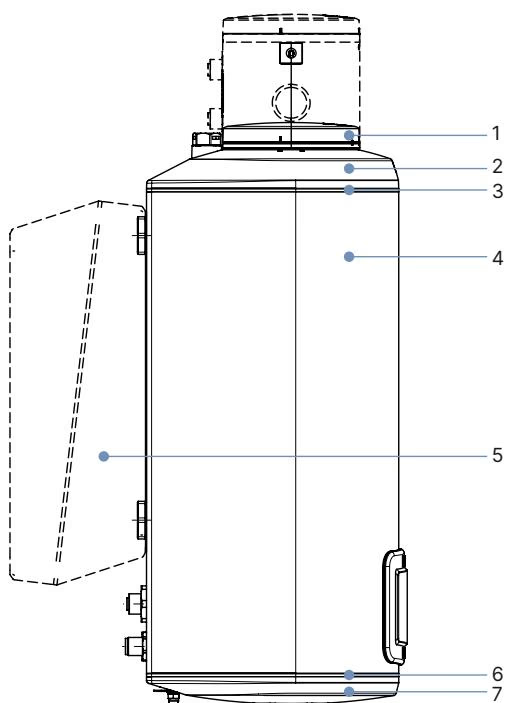
| Item | Actuator Component (AG2) | Material |
|---|---|---|
| 1 | Blind cover / housing top | PPS (Polyphenylene sulphide) |
| 2 | Actuator cover | PPS |
| 3 | Seal rings | EPDM |
| 4 | Actuator housing | Cast aluminium, powder-coated |
| 6 | Housing seal | EPDM |
| 7 | Actuator base | PPS |
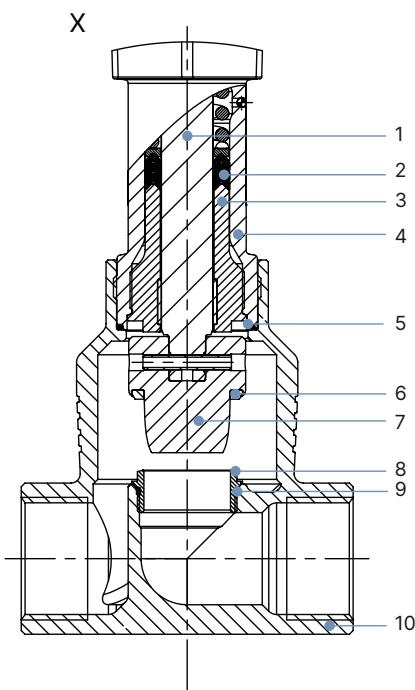
| Item | Valve Body Component | Material Specification |
|---|---|---|
| 1 | Spindle | Stainless steel 1.4401 (316) / 1.4404 (316L) |
| 2 | Spindle seal | PTFE V-seals (filled) with spring compensation |
| 3 | Spindle guide | Stainless steel 1.4404 (316L) |
| 4 | Packing gland tube | Stainless steel 1.4401 (316) |
| 5 | Body seal | Graphite or PTFE |
| 6 | Seat seal | Stainless steel 1.4571 |
| 7 | Control cone | Stainless steel 1.4571 |
| 8 | Valve seat | Stainless steel 1.4571 |
| 9 | O-ring for valve seat | EPDM or PTFE |
| 10 | Valve body | Stainless steel CF3M (cast 316L equivalent) |
All dimensions are specified in millimetres (mm). For closed-position clearance calculations, note that the AG2 actuator spindle raises the actuator head by approximately 2 mm when seated without tight sealing preload.
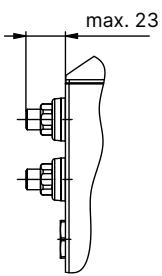
| Port Connection DN | NPS | Actuator Height H1 (Standard Variant) | Actuator Height H2 (Fieldbus Gateway Variant) |
|---|---|---|---|
| 10 (Article 339405) | 3/8 | 417 mm | 489 mm |
| 15 | 1/2 | 417 mm | 489 mm |
| 20 | 3/4 | 423 mm | 495 mm |
| 25 | 1 | 446 mm | 518 mm |
| 32 | 1 1/4 | 474 mm | 546 mm |
| 40 | 1 1/2 | 479 mm | 551 mm |
| 50 | 2 | 485 mm | 557 mm |
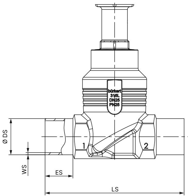
| Port Connection DN | Weld Depth ES | Face-to-Face Length LS | DIN EN ISO 1127 / ISO 4200 Outer ∅ DS | DIN EN ISO 1127 Wall Thickness WS | DIN 11850-2 Outer ∅ DS | DIN 11850-2 Wall Thickness WS |
|---|---|---|---|---|---|---|
| 10 (Article 339405) | 20 mm | 90 mm | 17.2 mm | 1.6 mm | 13.0 mm | 1.5 mm |
| 15 | 20 mm | 90 mm | 21.3 mm | 1.6 mm | 19.0 mm | 1.5 mm |
| 20 | 20 mm | 100 mm | 26.9 mm | 1.6 mm | 23.0 mm | 1.5 mm |
| 25 | 26 mm | 130 mm | 33.7 mm | 2.0 mm | 29.0 mm | 1.5 mm |
| 32 | 26 mm | 140 mm | 42.4 mm | 2.0 mm | 35.0 mm | 1.5 mm |
| 40 | 26 mm | 150 mm | 48.3 mm | 2.0 mm | 41.0 mm | 1.5 mm |
| 50 | 26 mm | 175 mm | 60.3 mm | 2.0 mm | 53.0 mm | 1.5 mm |
Article 339405 features an analogue control configuration with internal DIP switches, two push buttons, a 360° LED ring indicator, and a Service-büS port located underneath the removable blind cover.
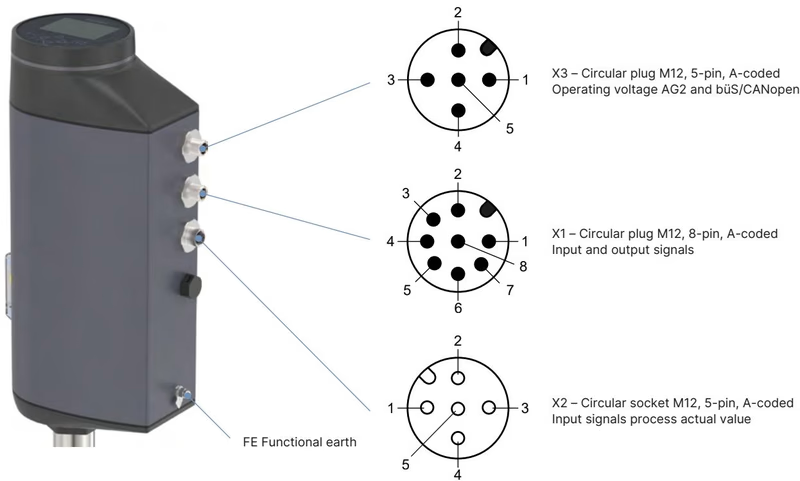
| Connector Designation | Physical Format | AG2 Analogue (Article 339405) | AG2 with Fieldbus Gateway | AG2 büS/CANopen Native |
|---|---|---|---|---|
| X1 | M12 circular plug, 8-pin, A-coded | Equipped (Analogue & Digital I/O) | Not equipped | Not equipped |
| X2 | M12 circular socket, 5-pin, A-coded | Optional (Process controller actual value) | Optional | Optional |
| X3 | M12 circular plug, 5-pin, A-coded | Equipped (24 V DC power & Service-büS) | Equipped | Equipped |
| X7 | M12 circular socket, 4-pin, D-coded | Not equipped | Equipped (Ethernet 2-port) | Not equipped |
| Connector X1 (8-pin M12 Male, A-coded) | Pin | Assigned Function |
|---|---|---|
| Input and Output Control Signals | 1 | Digital input + |
| 2 | GND for digital input and digital outputs | |
| 3 | Digital output 2 + | |
| 4 | Digital output 1 + | |
| 5 | Analogue output - | |
| 6 | Analogue output + | |
| 7 | Set-point value / Analogue input - | |
| 8 | Set-point value / Analogue input + |
| Connector X3 (5-pin M12 Male, A-coded) | Pin | Assigned Function |
|---|---|---|
| Supply Voltage & Service Communication | 1 | CAN Shield / shield |
| 2 | Operating voltage 24 V DC ±10% | |
| 3 | GND / CAN_GND | |
| 4 | CAN_H (büS) | |
| 5 | CAN_L (büS) |
Analogue and Digital Signal Parameters
Fluid flow is directed below the valve seat (flow path 2 → 1). This orientation prevents hydraulic water hammer upon closing.
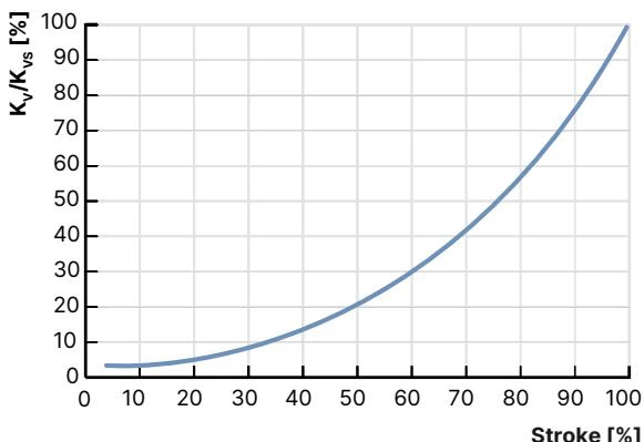
| Seat Size (Orifice) | Actuator Force [N] | Max Operating Pressure (Seat Seal Leakage Class) [bar] | Theoretical Rangeability | Kv Value at 10% Stroke | Kv Value at 30% Stroke | Kv Value at 50% Stroke | Kv Value at 70% Stroke | Kv Value at 90% Stroke | Nominal Kvs Value (100%) [m³/h] |
|---|---|---|---|---|---|---|---|---|---|
| 3 mm | 1,300 | 25 (IV) / 40 (IV) | 20:1 | 0.005 | 0.013 | 0.026 | 0.044 | 0.077 | 0.10 |
| 3 mm (high) | 1,300 | 25 (IV) / 40 (IV) | 20:1 | 0.009 | 0.023 | 0.046 | 0.085 | 0.160 | 0.20 |
| 4 mm | 1,300 | 25 (IV) / 40 (IV) | 30:1 | 0.023 | 0.049 | 0.097 | 0.180 | 0.350 | 0.50 |
| 6 mm (339405) | 1,300 | 25 (IV / VI) | 50:1 (Linear 25:1) | 0.007 | 0.045 | 0.160 | 0.410 | 1.100 | 1.25 (1.20 water) |
| 8 mm | 1,300 | 25 (VI) / 40 (VI) | 50:1 | 0.070 | 0.120 | 0.260 | 0.610 | 1.500 | 2.00 |
| 10 mm | 1,300 | 25 (VI) / 40 (VI) | 50:1 | 0.110 | 0.190 | 0.480 | 1.000 | 2.300 | 2.70 |
The maximum permissible ambient temperature depends directly on the process fluid temperature. Operating limits must adhere to the DIN EN 12516-1 PN 25 curve and ambient derating boundaries.
| Seat Seal Material | Leakage Class (DIN EN 60534-4) | Medium Temperature Range | Process Characteristics |
|---|---|---|---|
| Stainless Steel (Article 339405) | Class III / IV (Metal-to-metal) | -40 °C to +230 °C (339405 configured for -10 °C to +185 °C) | Impervious to harsh process media, cavitation, and erosion. Leakage rate: 0.1% to 0.01% of nominal flow. |
| PTFE | Class VI (Soft seal bubble-tight) | -40 °C to +130 °C (recommended ≤ +130 °C) | Tight shut-off without auxiliary isolation valves; sensitive to abrasive erosion. |
| PEEK | Class VI (Soft seal bubble-tight) | -10 °C to +230 °C (recommended > +130 °C) | High-temperature tight shut-off; sensitive to severe mechanical erosion. |
For AG2 actuators equipped with the SAFEPOS energy-pack (Curve 3 in the Burkert operating charts):
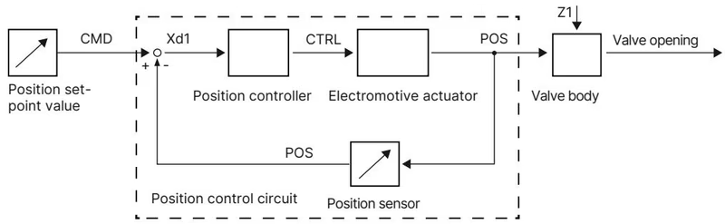
The positioning electronics calculate deviation Xd1 between external command setpoint CMD (from analogue input X1) and internal spindle displacement sensor actual value POS. The motor drives the ball screw via actuating variable CTRL until positioning deviation is zero.
The factory-fitted SAFEPOS energy-pack (article 285834 for AG2) stores electrical energy to drive the valve to a predetermined safe position upon power loss:
Manual operation can be performed electrically or mechanically:
Mechanical Manual Override Torque Restriction
Never exceed 2 Nm torque when operating the mechanical manual override. Exceeding 2 Nm upon reaching the stroke end stops damages the internal mechanical drive.
High Pressure and Hazardous Media Hazard
Before dismantling or servicing the valve, isolate pipeline pressure, vent the system, drain medium completely, and disconnect supply voltage. Wait until the 360° LED ring is extinguished to verify complete SAFEPOS capacitor discharge.
| Maintenance Joint | Applicable Size | Required Tightening Torque |
|---|---|---|
| Body Connection to Actuator | DN 10 / DN 15 (Article 339405) | 45 ±3 Nm (33 ±2 lbf·ft) |
| Spindle Guide Bushing Thread | DN 10 / DN 15 (Spindle ø10 mm) | 15 Nm |
| Actuator Base Housing Screws | AG2 (4 screws, crosswise) | 5 Nm |
| Valve Seat Ring Thread | DN 10 / DN 15 (Seat sizes 3 to 15 mm) | 20 Nm (+3 Nm tolerance) |
| SAFEPOS Retaining Screw | T10 Torx | 1.1 Nm |
Position Controller Calibration via X.TUNE
After replacing the control cone, seat, packing gland, or re-mounting the actuator on the valve body, execute the X.TUNE automatic calibration function.
| Accessory Description | Order Identification / Article Number |
|---|---|
| SAFEPOS energy-pack replacement module (AG2) | 285834 |
| Packing gland seal set (Spindle ø10 mm, DN 10 to DN 20) | 285685 |
| Stainless steel spindle guide (Spindle ø10 mm, Body DN 15/10) | 246577 |
| Control cone set (Seat 6 mm, DN 10/15, Steel/Steel) | 152696 |
| Valve seat ring set (Seat 6 mm, DN 10/15) | 262146 |
| Valve seat replacement installation tool (DN 15/10) | 652604 |
| Holding device for pipe connection DN 15 / DN 20 | 693770 |
| Plastic blind cover | 277881 |
| SIM card for device parameter backup and transfer | 291773 |
| M12 circular socket with 5 m cable, 4-pin A-coded (X3 power supply AG2) | 918038 |
| M12 circular socket with 2 m cable, 8-pin A-coded (X1 input/output signals) | 919061 |
| USB büS interface set 1 (includes power supply, büS stick, terminating resistor, Y-splitter) | 772426 |
| USB büS interface set 2 (includes büS stick, terminating resistor, Y-splitter) | 772551 |
| büS adapter cable for Service-büS interface (M12 to Micro-USB, 0.3 m) | 774931 / 773254 |
| Bürkert Communicator configuration software | Type 8920 (Free download from www.burkert.com) |
Explore similar products in our catalog


