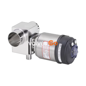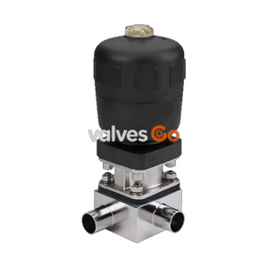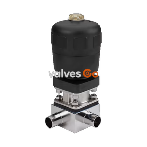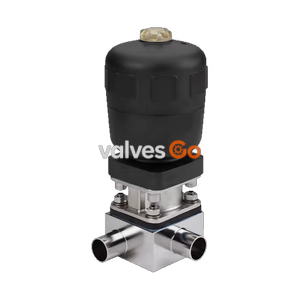
Type 2032

BURKERT 348414 (Type 2031) 2/2-way pneumatic diaphragm valve features a PPS piston actuator, ASME BPE 1 1/2" clamp ports, PTFE/EPDM diaphragm, and normally open control function B for sterile fluid processes.
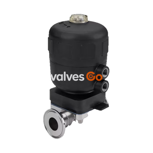
BURKERT 348414 (Type 2031) is an externally piloted 2/2-way diaphragm valve engineered for ultra-pure, sterile, aggressive, and abrasive fluid duties in pharmaceutical, biotechnical, and hygienic process lines. Operating under control function B (CF B), the valve is held open in its unpressurised rest state by internal spring tension and closes upon pneumatic pressurisation through the upper pilot air connection. The valve body is constructed from forged stainless steel alloy 1.4435 (316L, conforming to ASME BPE / BN2 DIN EN 10222-5) and features 1 1/2" ASME BPE sanitary clamp ends (clamp outer diameter 50.5 mm, tube outer diameter 38.1 mm, wall thickness 1.65 mm). Zero-dead-leg geometry and flow-optimised contouring yield a water Kv coefficient of 37.5 m³/h.
The process interface is sealed by a two-piece PTFE/EPDM diaphragm (order code EA) mounted via a twist-and-lock bayonet mechanism, isolating operating fluids from the mechanical drive components. Drive actuation is managed by an autoclavable polyphenylene sulphide (PPS) piston actuator equipped with an integrated optical stem position indicator, fluor rubber (FKM) piston seals, and G 1/4" female pilot air ports. The valve handles operating pressures from 0 to 10 bar, working temperatures from -10 °C to +130 °C, and steam sterilization cycles up to +140 °C for 60 minutes. Standard delivery includes a manufacturer 3.1 inspection certificate and a 2.1 diaphragm declaration.
| Specification Parameter | Technical Value / Detail |
|---|---|
| Model Number / Resource SKU | 348414 (Type 2031 CLASSIC series) |
| Valve Type | Pneumatically operated 2/2-way diaphragm valve, complete assembly |
| Switching Positions / Ports | 2 switching positions / 2 fluidic ports |
| Control Function | Function B (CF B / SFB): Bidirectional, normally open by spring force |
| Nominal Diameter (DN) | DN 40 (1 1/2" / 1.5 Inch) |
| Diaphragm Size | Diaphragm size 40 |
| Body Port Connection | ASME BPE Clamp (DIN 11866 series C) |
| Port 1 Outer Diameter (OD) | 38.1 mm (1 1/2") |
| Port 1 Inner Diameter (ID) | 34.8 mm |
| Port 1 Wall Thickness (s) | 1.65 mm (0.065") |
| Clamp Flange Outer Diameter | 50.5 mm (1.984") |
| Nominal Pressure Rating | PN 16 (DIN EN 1333) / Class 150 (DIN EN 1759) |
| Operating Medium Pressure | 0.00 bar to 10.00 bar (gauge pressure) |
| Pilot Control Pressure Range | 2.0 bar to 7.0 bar (pilot medium: neutral gases, dry instrument air) |
| Flow Coefficient Kv (Water) | 37.5 m³/h (+20 °C, 4 bar inlet, 3 bar outlet) |
| Medium Temperature Limits | -10 °C to +130 °C (steam sterilisation: +140 °C for 60 min) |
| Ambient Temperature Limits | +5 °C to +90 °C (short-term exposure up to +140 °C) |
| Valve Body Material | Forged stainless steel 1.4435 / 316L (BN2 / ASME BPE) |
| Internal Surface Roughness | Ra ≤ 0.38 µm (ASME BPE SF4 electropolished) / Ra ≤ 0.5 µm (SF1 mechanical) |
| Actuator Housing Material | Polyphenylene sulphide (PPS) |
| Diaphragm Material | PTFE with EPDM backing membrane (EA) |
| Piston Seal Material | FKM (Fluor rubber) |
| Pilot Air Connection | G 1/4" internal thread (stainless steel 1.4305 port insert) |
| Manual Override | None |
| Cleaning Capabilities | Full CIP (Clean-in-Place) and SIP (Steam-in-Place) capable |
| Compliance & Certificates | 3.1 Inspection Certificate, 2.1 Membrane Certificate, FDA, USP Class VI, EC 1935/2004 |
BURKERT 348414 is composed of a forged stainless steel 2-way body, a hygienic diaphragm seal, and a compact piston actuator. Internal fluid-contacting surfaces are finished to sanitary roughness grades to eliminate bacterial accumulation and cross-contamination risks.
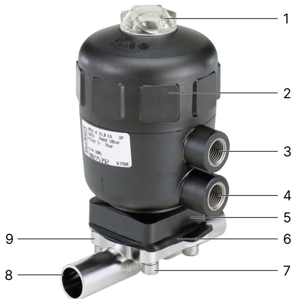
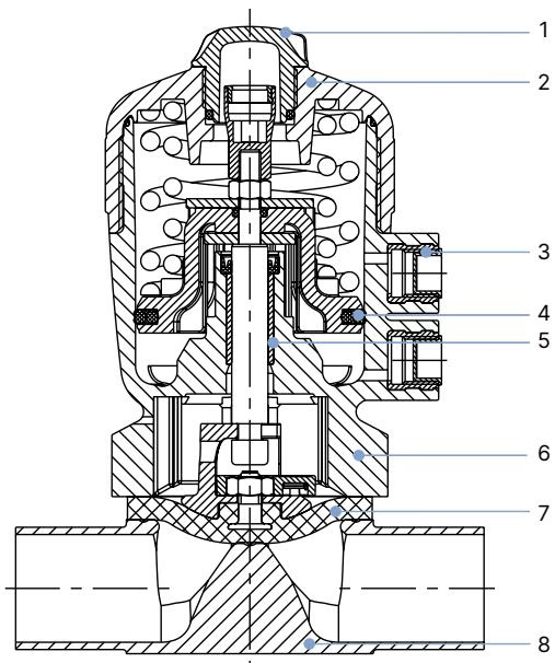
| Item No. | Valve Element | Material Specification |
|---|---|---|
| 1 | Transparent Cap / Position Visualisation | Polysulfone (PSU) |
| 2 | Actuator Cover | Polyphenylene sulphide (PPS) standard (PA available on request) |
| 3 | Pilot Air Ports | Stainless steel 1.4305 (G 1/4" female) |
| 4 | Piston Seal | Fluor rubber (FKM) |
| 5 | Socket / Guiding Element | Sinter metal |
| 6 | Interface / Actuator Base | Polyphenylene sulphide (PPS) standard (1.4404 on request) |
| 7 | Process Diaphragm | PTFE with EPDM backing cushion (code EA) |
| 8 | Valve Body | Forged stainless steel 1.4435 / 316L (BN2, ASME BPE) |
Hygienic Process Diaphragm
The diaphragm on BURKERT 348414 uses an inert PTFE process contact shield supported by a vulcanised EPDM backing cushion. The compound complies with FDA 21 CFR 177.1550 and 177.2600, passes USP Class VI biocompatibility testing, and adheres to European Regulation EC 1935/2004 for food contact materials.
BURKERT 348414 is configured with Control Function B (CF B / SFB). The actuator contains internal compression springs configured to drive the piston and spindle upward in the absence of control air, holding the valve fully open.
Pneumatic Port Selection
Never apply pilot air to the lower port on a CF B valve during operational switching. The lower port vents air from beneath the piston. Connecting pilot pressure to the incorrect port prevents closing and causes process disruption.
The forged valve body conforms to ASME BPE hygienic clamp dimensions, featuring standardized end-to-end lengths and clamp face geometry.
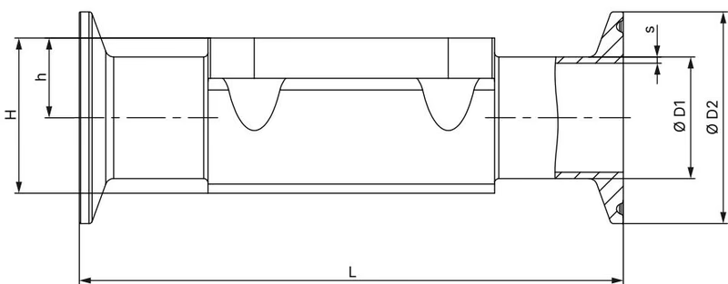
| Dimension Designation | Symbol | Dimension [mm] | Dimension [Inch] |
|---|---|---|---|
| Nominal Port Diameter | DN | 40 mm | 1 1/2" (1.5") |
| Diaphragm Size | DS | 40 mm | — |
| Tube Outer Diameter | ∅ D1 | 38.10 mm | 1.500" |
| Tube Wall Thickness | s | 1.65 mm | 0.065" |
| Tube Inner Diameter | ID | 34.80 mm | 1.370" |
| Clamp Flange Outer Diameter | ∅ D2 | 50.50 mm | 1.984" |
| Face-to-Face Body Length (TG05 standard) | L | 140 mm | 5.512" |
| Face-to-Face Body Length (TG05 + AF34 long version) | L | 159 mm | 6.260" |
| Weir Height to Port Axis | h | 27.60 mm | 1.087" |
| Body Centerline to Actuator Interface | H | 52.40 mm | 2.063" |
For diaphragm size 40, Type 2031 utilises actuator size 100 (G) or 125 (H) with G 1/4" pilot air connections:
| Actuator Size | Outer Diameter ∅ A [mm] | Height C [mm] | Air Port K | Total Actuator Height H [mm] | Height with MT85 Block [mm] | Total Height with Type 8697 [mm] |
|---|---|---|---|---|---|---|
| 100 (G) | 127 | 73 | G 1/4" | 205 | 246 | 298 (HM) / 339 (HM+MT85) |
| 125 (H) | 158 | 86 | G 1/4" | 243 | 284 | 336 (HM) / 377 (HM+MT85) |
Flow rate data is established in accordance with DIN EN 60534 standards at +20 °C fluid temperature, with 4 bar at the valve inlet and 3 bar at the outlet (Δp = 1 bar).
| Diaphragm Size | Connection Standard | Pipe Size | Water Kv Value (Elastomer) | Water Kv Value (PTFE/EPDM) |
|---|---|---|---|---|
| 40 | ASME BPE (DIN 11866 C) | 1 1/2" (38.1 x 1.65 mm) | 37.0 to 40.0 m³/h | 37.5 m³/h |
| 40 | DIN EN ISO 1127 (B) | DN 32 / DN 40 | 41.0 m³/h | 40.0 m³/h |
| 40 | DIN 11850 Series 2 (A) | DN 40 (41.0 x 1.5 mm) | 40.0 m³/h | 40.0 m³/h |
| 40 | SMS 3008 | DN 40 (38.0 x 1.2 mm) | 38.0 m³/h | 38.0 m³/h |
Under control function B, the valve achieves bidirectional shut-off up to 10.0 bar static line pressure when pilot air is supplied within the allowable 2.0 to 7.0 bar range. To maximize diaphragm service life, the pilot pressure supplied to the upper port should not exceed the level necessary to reliably close the process medium pressure.
BURKERT 348414 can be installed in any orientation; positioning the actuator vertically upright is recommended. When installed horizontally, the valve must be angled around the pipe axis to ensure gravity self-draining without pooling behind the weir.
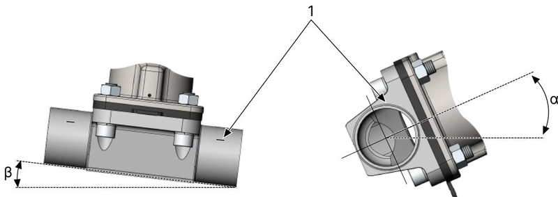
The PPS actuator is maintenance-free under normal operating conditions. Regular maintenance requires periodic visual inspection of the leakage bore and inspection of the PTFE/EPDM diaphragm every 100,000 cycles, or sooner if handling abrasive fluids.
Stored Energy and Depressurisation Hazard
Before loosening body screws or clamp connections, isolate the pipeline, depressurise both fluid and pneumatic lines, and allow the system to drain and cool. Valves with Control Function B contain preloaded compression springs beneath the piston. Do not attempt to dismantle the actuator cylinder housing without an authorized fixture.
| Diaphragm Size | Port DN | Valve Body Type | Tightening Torque (PTFE/EPDM) | Tightening Torque (EPDM/FKM) |
|---|---|---|---|---|
| 40 | DN 40 (1 1/2") | Forged Body (VS) | 10.0 Nm (+10% tolerance) | 8.0 Nm (+10% tolerance) |
| Symptom / Malfunction | Root Cause | Corrective Action |
|---|---|---|
| Actuator fails to open | Upper pilot port remained pressurized; pilot air supply exhausted | Vent upper pilot air port; check compression spring integrity |
| Actuator fails to close | Pilot air connected to lower port instead of upper port | Reconnect pilot line to upper port (SFB closes via upper port) |
| Valve leaks past seat | Pilot pressure too low to overcome line pressure; line pressure exceeds 10 bar | Increase pilot pressure within 2.0–7.0 bar range; verify line pressure |
| External leakage at body flange | Body screws untorqued after steam cycle; diaphragm cold-flowed | Re-torque body screws crosswise to 10.0 Nm in pressurized state |
| Fluid leaks from bonnet relief hole | Worn or ruptured PTFE/EPDM diaphragm | Immediately replace diaphragm (Order number 20093073) |
| Flow rate significantly reduced | Distorted or bulging PTFE diaphragm from overheating or vacuum | Replace diaphragm; avoid using diaphragm as primary steam stop |
Original BURKERT spare parts maintain technical conformity and hygiene certifications:
| Component Description | Type / Size Detail | Order Article Number |
|---|---|---|
| Replacement Diaphragm PTFE/EPDM (EA) | Diaphragm Size 40 (EPDM E04 / PTFE P05 bayonet) | 20093073 |
| Replacement Diaphragm EPDM (AD) | Diaphragm Size 40 (EPDM E04 threaded with insert) | 688426 |
| Replacement Diaphragm GYLON® (ER) | Diaphragm Size 40 (PTFE L08 laminate) | 693180 |
| Actuator Seal Set (PPS Actuator) | Actuator Size 100 (G), Diaphragm Size 40 | 012127 |
| Actuator Seal Set (PPS Actuator) | Actuator Size 125 (H), Diaphragm Size 40 | 011494 |
| Actuator Cover Installation Wrench | Tool for Actuator Cover ∅ 100 mm / 125 mm | 639172 / 639173 |
| Control Function Conversion Kit (CF A → CF B) | Actuator Size 100 (G) / Actuator Size 125 (H) | 011710 / 011715 |
| Integrated Position Feedback Module | Type 8697 (Inductive or mechanical limit switches) | Consult Bürkert Type 8697 |
| Integrated Process Automation Head | Type 8690 (Decentralised pilot valve / feedback) | Consult Bürkert Type 8690 |
Explore similar products in our catalog