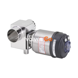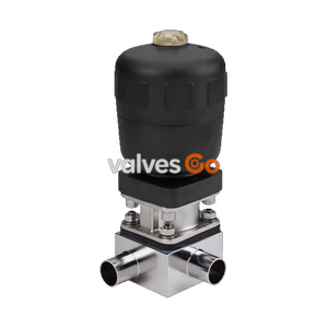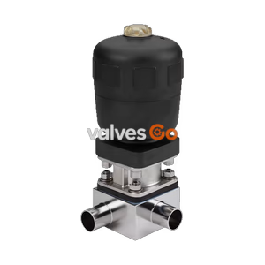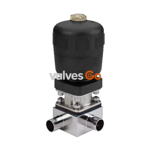
Type 2032

Burkert 350272 (Type 2031) is an externally controlled 2/2-way diaphragm valve with pneumatic PPS actuator, high-temperature EPDM seal, and ASME BPE 3/8" weld connection for sterile media.
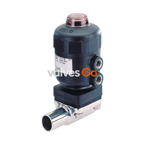
Burkert 350272 (Type 2031) is an externally controlled 2/2-way diaphragm valve with a pneumatic piston actuator, an EPDM diaphragm, and a forged stainless steel valve body. Designed for ultra-pure, sterile, and aggressive media, it operates in control function A (normally closed by spring force) across an operating pressure range of 0 to 10 bar. The unit features an ASME BPE / DIN 11866 Series C weld connection in size 3/8 inch (DN 10, pipe dimensions 9.53 x 0.89 mm) and provides a water flow factor (Kv value) of 1.6 m³/h.
Manufactured with a polyphenylene sulphide (PPS) actuator housing in size 40 mm (actuator code C), Burkert 350272 is autoclavable and withstands ambient temperatures up to +140 °C. The flow-optimized forged body (type VS) has minimal dead space and meets strict hygienic requirements, featuring full CIP and SIP cleanability with steam sterilization resistance up to +150 °C for 60 minutes.
Burkert 350272 uses control function A (CF A). In the de-energized rest position, integrated compression springs generate the closing force on the piston actuator. A spindle transmits this closing force directly to the compressor, pressing the elastomeric diaphragm tightly against the weir in the valve body to shut off fluid flow in both directions.
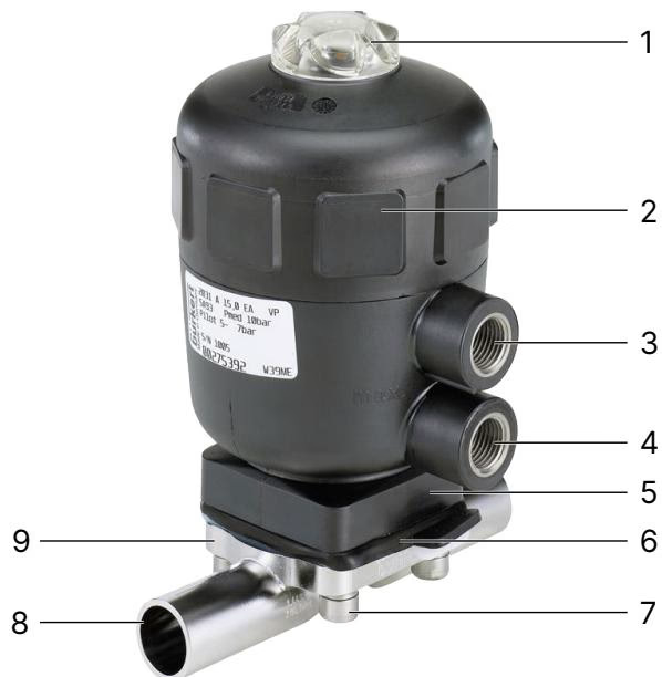
Applying pilot pressure (5.0 to 7.0 bar) to the lower pilot air port compresses the spring pack, lifting the piston, spindle, compressor, and diaphragm away from the weir to open the flow path. When the pilot port is vented, spring force returns the diaphragm to its closed position.
| Position | Component | Description |
|---|---|---|
| 1 | Transparent cap | Visual position indicator cap made of polysulfone (PSU) |
| 2 | Actuator cover | Polyphenylene sulphide (PPS) housing cover |
| 3 | Upper pilot air port | G 1/8 port (used for CF B and CF I) |
| 4 | Lower pilot air port | G 1/8 port for CF A (applies pilot pressure to open the valve) |
| 5 | Diaphragm bonnet | Intermediate housing interface |
| 6 | Diaphragm | High-temperature EPDM sealing diaphragm (size 8) |
| 7 | Body screws | Fasteners securing actuator assembly to valve body |
| 8 | Port connection | ASME BPE 3/8" weld ends |
| 9 | Valve body | Forged stainless steel weir body (1.4435 / 316L) |
| Parameter | Specification |
|---|---|
| Burkert Article Number | 350272 |
| Valve Type | 2031 CLASSIC |
| Configuration | 2/2-way on/off valve |
| Control Function | CF A: Normally closed by spring force |
| Actuator Size | Ø 40 mm (Actuator C) |
| Actuator Housing Material | Polyphenylene sulphide (PPS) |
| Body Construction | Forged valve body (VS) |
| Body Material | Stainless steel 1.4435 (BN2 / 316L) |
| Diaphragm Size (DS) | 8 mm |
| Diaphragm Material | EPDM high-temperature (Code AD / E04) |
| Piston Seal Material | Fluor rubber (FKM) |
| Connection Standard | ASME BPE / DIN 11866 Series C (Port Code SA91) |
| Connection Size | DN 10 (3/8") |
| Pipe Dimensions | Outer Ø 9.53 mm, Inner Ø 7.75 mm, Wall thickness 0.89 mm (0.035") |
| Flow Rate (Kv water at +20 °C) | 1.6 m³/h |
| Operating Pressure Range | 0 to 10 bar (static / dynamic) |
| Pilot Pressure Range | 5.0 to 7.0 bar |
| Nominal Pressure Class | PN 16 / Class 150 |
| Medium Temperature | -10 °C to +143 °C (steam sterilization up to +150 °C for 60 min) |
| Ambient Temperature | +5 °C to +140 °C |
| Pilot Air Connection | G 1/8 internal thread |
| Pilot Control Medium | Neutral gases, filtered compressed air |
| Cleaning Capabilities | CIP capable, SIP capable |
| Standard Compliance | Manufacturer test certificate 3.1, Membrane factory certification 2.1, FDA, USP Class VI, EC 1935/2004 |
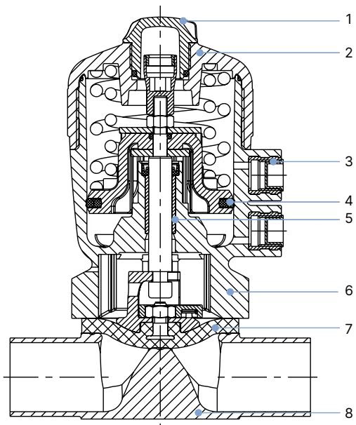
| Item | Element | Material |
|---|---|---|
| 1 | Transparent cap | Polysulfone (PSU) |
| 2 | Cover | Polyphenylene sulphide (PPS) |
| 3 | Pilot air ports | Stainless steel 1.4305 |
| 4 | Piston seal | Fluor rubber (FKM) |
| 5 | Socket | Sintered metal |
| 6 | Interface / Bonnet | Polyphenylene sulphide (PPS) |
| 7 | Diaphragm | EPDM (AD) high-temperature |
| 8 | Valve body | Forged stainless steel 1.4435 (BN2 / 316L) |
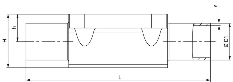
| Diaphragm Size | Port Connection DN | Outer Ø D1 [mm] | Wall Thickness s [mm] | Body Length L [mm] | Height h [mm] | Body Height H [mm] | Product Key |
|---|---|---|---|---|---|---|---|
| 6 | 1/4" | 6.35 | 0.89 | 78 | 5.7 | 15.2 | SA90 |
| 6 | 3/8" | 9.53 | 0.89 | 89 | 5.7 | 15.2 | SA91 |
| 6 | 1/2" | 12.70 | 1.65 | 89 | 9.3 | 18.8 | SA92 |
| 8 (Model 350272) | 1/4" | 6.35 | 0.89 | 78 | 5.7 | 15.2 | SA90 |
| 8 (Model 350272) | 3/8" | 9.53 | 0.89 | 89 | 5.7 | 15.2 | SA91 |
| 8 (Model 350272) | 1/2" | 12.70 | 1.65 | 89 | 9.3 | 18.8 | SA92 |
| 15 | 1/2" | 12.70 | 1.65 | 108 | 8.15 | 19.85 | SA92 |
| 15 | 3/4" | 19.05 | 1.65 | 108 | 12.05 | 23.75 | SA93 |
| 20 | 3/4" | 19.05 | 1.65 | 117 | 16.0 | 30.3 | SA93 |
| 25 | 1" | 25.40 | 1.65 | 127 | 19.0 | 37.0 | SODF |
Flow rate values correspond to Kv water flow in m³/h measured at +20 °C with 4 bar valve inlet pressure and 3 bar valve outlet pressure for elastomeric diaphragms.
| Diaphragm Size | Port DN [mm] | Port DN [inch] | DIN EN ISO 1127 (Series B) | DIN 11850-2 (Series A) | ASME BPE (Series C) | BS 4825 |
|---|---|---|---|---|---|---|
| 6 | 8 | 1/4" | 2.2 | - | 0.7 | - |
| 6 | 10 | 3/8" | - | 2.0 | 1.6 | - |
| 8 | 8 | 1/4" | 1.5 | - | 0.7 | 0.5 |
| 8 (Model 350272) | 10 | 3/8" | 1.5 | 1.5 | 1.6 | 1.4 |
| 8 | 15 | 1/2" | - | - | 1.9 | - |
| 15 | 15 | 1/2" | 6.5 | 6.5 | 3.1 | 3.7 |
| 20 | 20 | 3/4" | 12.5 | 12.4 | 8.4 | 8.9 |
| 25 | 25 | 1" | 18.0 | 20.0 | 15.5 | 15.5 |
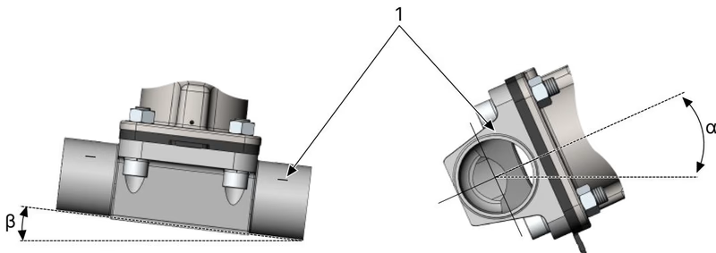
Burkert 350272 can be mounted in any orientation, but positioning the pneumatic actuator upright is recommended. For complete hygienic gravity draining, the installation must adhere to specific alignment angles:
Self-Draining Angle for SA91
For forged valve bodies with ASME BPE / DIN 11866 Series C weld ends, port code SA91 (DN 10 / 3/8", pipe dimensions 9.53 x 0.89 mm, diaphragm size 8), the determined self-draining angle α is exactly 39°.
Welding Precaution
Before welding the forged body into the pipeline, the pneumatic actuator and diaphragm must be completely removed from the body. Thermal exposure during welding will permanently destroy the EPDM diaphragm and internal actuator seals. Reinstall the actuator assembly only after the weld seams have cooled down and the piping has been flushed.
Fastening body screws requires crosswise, stepped tightening to ensure uniform perimeter compression of the EPDM diaphragm.
| Diaphragm Size | Forged Body (VS), Cast (VG), Plastic [Nm] (EPDM / FKM) | Forged Body (VS), Cast (VG), Plastic [Nm] (PTFE / GYLON®) | Tube Body (VP) [Nm] (EPDM / FKM) | Tube Body (VP) [Nm] (PTFE / GYLON®) |
|---|---|---|---|---|
| 6 | 1.1 | 1.1 | - | - |
| 8 (Model 350272) | 2.0 | 2.5 | 2.0 | 2.5 |
| 15 | 3.5 | 4.0 | 3.5 | 4.0 |
| 20 | 4.0 | 4.5 | 4.0 | 4.5 |
| 25 | 5.0 | 6.0 | 7.0 | 8.0 |
| 32 | 6.0 | 8.0 | 8.0 | 10.0 |
| 40 | 8.0 | 10.0 | 12.0 | 15.0 |
| 50 | 12.0 | 15.0 | 15.0 | 20.0 |
| 65 | 20.0 | 30.0 | 20.0 | 30.0 |
All specified tightening torque values have an engineering tolerance of +10%.
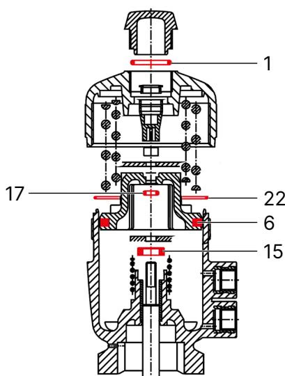
The pneumatic actuator is maintenance-free under normal operating conditions. Regular maintenance focuses on inspection of wearing parts (seals and diaphragm):
Diaphragm size 8 uses a buttoned fastening mechanism. To replace the diaphragm on CF A valves:
| Item | Description | Actuator / DS | Order Number |
|---|---|---|---|
| Seal set | Complete internal actuator seal set (FKM / NBR) | PPS Actuator 40 (C) / DS 8 | 011465 |
| Replacement diaphragm | EPDM high-temperature diaphragm (AD / material code E04) | Diaphragm size 8 | 688421 |
| Actuator wrench | Service wrench for actuator housing cover | Actuator size 40 (C) | 639175 |
Explore similar products in our catalog