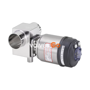
Type 2032

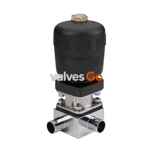
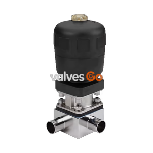
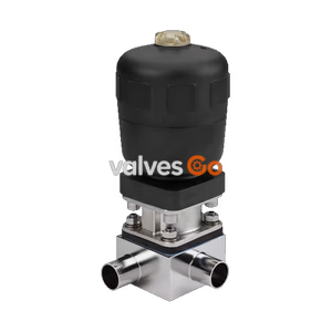
BURKERT 359949 (Type 2104) is a DN 25 pneumatic 3/2-way T-diaphragm valve with ASME BPE weld ends, normally closed actuator, GYLON/EPDM seal, and 0-10 bar rating.
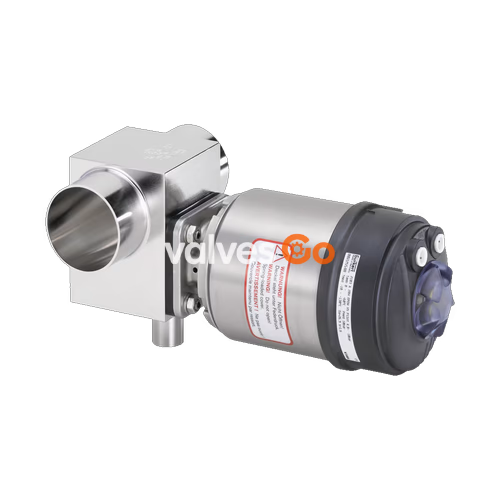
BURKERT 359949 (Type 2104) is an externally controlled pneumatic 3/2-way T-diaphragm valve designed for decentralised process automation in hygienic, sterile, and aggressive media applications. Built with an ASME BPE / DIN 11866 Series C DN 25 welded block body, this configuration operates under control function A (normally closed by internal spring pack). The valve assembly features a stainless steel envelope over a PPS actuator piston core, providing ingress protection to IP65/IP67 and NEMA Type 4X. Internal fluid contact surfaces are sealed with a GYLON® diaphragm laminated to an EPDM backing cushion, certified to FDA, USP Class VI, and EC 1935/2004 standards.
Operating pressure spans 0 to 10 bar (PN 16 rating, ASME Class 150), actuated by pneumatic pilot air at 5.5 to 7 bar via an integrated 6 mm push-in ELEMENT interface. The zero-deadleg T-body design is self-draining when mounted in recommended orientations, maintaining full CIP (clean-in-place) and SIP (sterilisation-in-place) compliance up to +140 °C for 60 minutes.
Article 359949 operates within defined pneumatic, thermal, and mechanical parameters:
| Technical Parameter | Specification |
|---|---|
| Article Number / Type | 359949 / Type 2104 |
| Fluidic Configuration | 3 ports, 2 switching positions (3/2-way T-valve) |
| Control Function | Control function A (CF A, normally closed by spring force) |
| Nominal Diameter (DN) | DN 25 (1 inch, 25.4 mm outer diameter) |
| Pipe Specification | ASME BPE / DIN 11866 Series C (25.4 x 1.65 mm, ID 22.1 mm) |
| Nominal Pressure Range | 0 bar to 10 bar (PN 16 according to DIN EN 1333 / Class 150 to DIN EN 1759) |
| Pilot Pressure Range | 5.5 bar to 7 bar (maximum pilot pressure 10 bar) |
| Medium Temperature | -5 °C to +130 °C (steam sterilisation to +140 °C for max. 60 min) |
| Ambient Temperature | -5 °C to +55 °C |
| Diaphragm Material | GYLON® laminated with EPDM support membrane (ER material code) |
| Valve Body Material | Stainless steel block material 1.4435 (316L) |
| Actuator Housing Material | Polyphenylene sulphide (PPS) with 1.4561 (316Ti) stainless steel casing |
| Pilot Air Connection | Push-in connector for 6 mm OD tubing (Interface ELEMENT) |
| Certifications Enclosed | EN 10204 3.1 inspection certificate, factory certification 2.1 diaphragm |
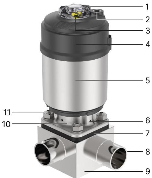
Type 2104 separates the operating pilot air from the ambient environment via integrated internal air ducts, preventing intake of aggressive process atmospheres. The bonnet features an inspection relief bore that immediately indicates any diaphragm leakage.
| Item | Component | Material |
|---|---|---|
| 1 | Ground terminal | Stainless steel 1.4301 / 1.4305 (on ATEX/IECEx variants) |
| 2 | Transparent cap | Polysulfone (PSU) with optical position indicator |
| 3 | Pilot air ports | Push-in connector PP (6 mm OD) / G 1/8 stainless steel 1.4305 |
| 4 | Actuator housing | Polyphenylene sulphide (PPS) |
| 5 | Actuator casing | Stainless steel 1.4561 (316Ti) |
| 6 | Piston seal | FKM |
| 7 | Diaphragm | GYLON® laminated with EPDM support membrane (ER) |
| 8 | Diaphragm bonnet | Stainless steel CF3M |
| 9 | Valve body | Stainless steel block material 1.4435 / 316L |
| 10 | Body fasteners | Stainless steel hex screws |
Steam Sterilisation Parameters
The GYLON®/EPDM laminated diaphragm accommodates saturated steam cycles up to +140 °C for a duration of 60 minutes. Extending steam cycles beyond this limit accelerates polymer fatigue and requires shortened inspection intervals.
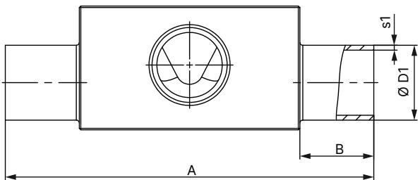
Dimensions for article 359949 correspond to diaphragm size 25 with ASME BPE / DIN 11866 Series C welded branch geometry:
| Parameter | Dimension (mm) | Description |
|---|---|---|
| Port 1 – Port 2 DN | 25...25 | Main line and branch diameter DN 25 (1 inch) |
| ∅D1 x s1 | 25.40 x 1.65 | Main run tube outside diameter and wall thickness |
| ∅D2 x s2 | 25.40 x 1.65 | Branch tube outside diameter and wall thickness |
| A | 124.5 | Overall body length |
| B | 25.0 | Weld end tangent length |
| C | 74.8 | Centreline to weir sealing face distance |
| E | 25.0 | Branch port tangent length |
| F | 95.0 | Total height from lower port edge to branch end |
| G | 42.0 | Distance from main centreline to body shoulder |
| H | 26.0 | Internal weir centre offset |
| I | 6.0 | Deadleg depth to weir seal seat |
| Product Key | SODF-SODF | Port connection configuration key |
For diaphragm size 25 with actuator size 70 (M, ∅92 mm cover) or size 90 (N, ∅120 mm cover), total valve height to the manual indicator cap (H+M) is 172 mm (actuator 70) or 205 mm (actuator 90). When fitted with a Type 8691 control head, height extends to 268 mm (actuator 70) or 301 mm (actuator 90).
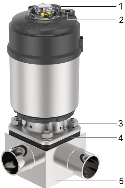
Damage to Actuator and Diaphragm during Welding
Direct welding with the actuator installed transfers destructive heat into the PPS housing, piston seals, and GYLON® diaphragm. Disassemble the actuator and diaphragm prior to welding the valve body into the line.
Leakage Detection Alignment
During horizontal or tilted pipeline installation, orient the valve body so that at least one relief bore in the diaphragm bonnet sits at the lowest downward point. This ensures immediate gravity drainage and detection should any medium leak past the primary seal.
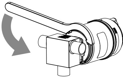
On valves with a stainless steel diaphragm bonnet, the actuator housing can be rotated continuously through 360° to optimize pilot air and electrical cable entry:
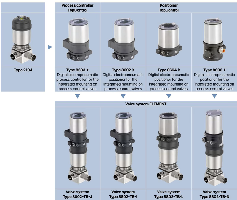
Type 2104 forms modular automated assemblies without external piping using the ELEMENT interface:
The pneumatic piston actuator is maintenance-free under specified service conditions. The GYLON® diaphragm and FKM piston O-rings are natural wearing components requiring scheduled inspection:
Elastomeric and polymer spare parts should be kept in airtight protective bags between +5 °C and +25 °C with relative humidity below 65%. Store diaphragms in an uncompressed state away from direct sunlight, UV fixtures, and ozone-generating electrical equipment.
Explore similar products in our catalog