


Up to 99.8% Efficiency

BURKERT 388757 (Type 3361) electromotive 2-way globe control valve features stainless steel construction, G 1/2 connection, 1300 N driving force, 24 V DC power, and integrated SAFEPOS emergency reset.
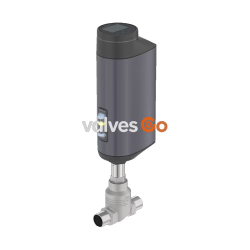
BURKERT 388757 (Type 3361) is an electromotive 2-way globe control valve engineered for demanding process automation. Equipped with a stainless steel body, G 1/2 internal thread connection (DN 15), and an 8 mm (5/16") seat diameter, fluid flows in below the seat to ensure stable throttling control. The electromotive linear actuator generates 1300 N driving force (AG2) on a 24 V DC power supply, delivering a typical closing time of 3,400 ms. The stainless steel control cone provides an equal percentage 50:1 flow characteristic with a rated water Kv of 2.1 m³/h (Cv 2.4 gpm). Operating pressures range from 0 to 25 bar (PN 25 / Class 150), and process media temperatures extend from -10 °C to +185 °C.
Positioning and process control functionality are governed by integrated digital electronics featuring an illuminated display with pushbuttons, Service-büS communication, and comprehensive I/O (1 analogue input, 1 digital input, 1 process value input, 1 analogue output, and 2 digital outputs). The actuator housing is constructed from powder-coated aluminium and polyphenylene sulphide (PPS), sealed to IP65/IP67 and NEMA 4X. A factory-installed SAFEPOS energy pack provides internal electrical storage, automatically closing the valve if main electrical power is interrupted.
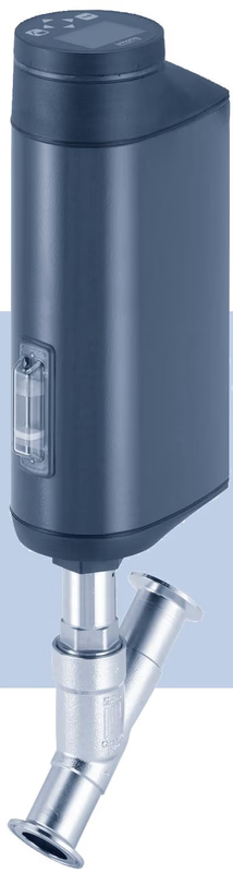
| Attribute | Technical Specification |
|---|---|
| Valve Type / Model | Type 3361 / Article 388757 |
| Flow Construction | 2-way globe valve, flow below seat |
| Nominal Port Diameter | G 1/2 internal thread (DN 15) |
| Seat Diameter / Orifice | 8 mm (5/16") |
| Flow Capacity | Kv 2.1 m³/h (water) / Cv 2.4 gpm |
| Control Characteristic | Equal percentage 50:1 |
| Operating Pressure Range | 0.00 bar to 25.00 bar (PN 25 / Class 150) |
| Medium Temperature Range | -10 °C to +185 °C |
| Operating Ambient Temperature | -25 °C min. (Storage: -40 °C to +70 °C) |
| Supply Voltage | 24 V DC |
| Actuator Size / Force | AG2 (1300 N electromotive thrust) |
| Typical Closing Time | 3,400 ms |
| Control Function | Normally closed (NC), electrical energy storage |
| Materials | Body: Stainless steel; Seat seal: Stainless steel; Actuator: Powder-coated aluminium / PPS |
| Protection Rating | IP65 / IP67, NEMA 4X |
| Regulatory Conformity | Food (EC) 1935/2004 compliant |
Original replacement parts preserve the calibration and sealing geometry of the Type 3361 globe valve body. The replacement sets for Type 3361 include control cone sets, valve seat sets, packing gland seal sets, and spindle guides.
| Component Description | Model Specifics (DN 15 / Seat 8) | Order Number |
|---|---|---|
| Control cone set (steel/steel) | Seat size 8, Orifice DN 10/15 (includes cone, dowel pin, graphite seal) | 149 935 |
| Valve seat set | Seat size 8, Orifice DN 10/15 (includes valve seat, graphite seal) | 262 147 |
| Packing gland seal set | Spindle ø10 mm, DN 15–DN 20 | 285 685 |
| VA spindle guide for packing gland | Spindle ø10 mm, Body DN 15 | 246 577 |
| SAFEPOS energy-pack | Replacement emergency power pack | 285 834 |
| Plastic display module | Replacement HMI module | 277 869 |
| Plastic dummy cover | Actuator top cover without display | 277 881 |
| Installation tool for valve seat | Seat replacement tool DN 15 | 652 604 |
| Modified socket wrench for packing gland | Spindle ø10 mm, DN 15 (Wrench size SW19) | 683 220 |
| Pipe connection holding device | Body clamping tool DN 15–DN 20 | 693 770 |
Type 3361 operates in either AUTOMATIC or MANUAL mode. Setting the operating state depends on the device hardware configuration:
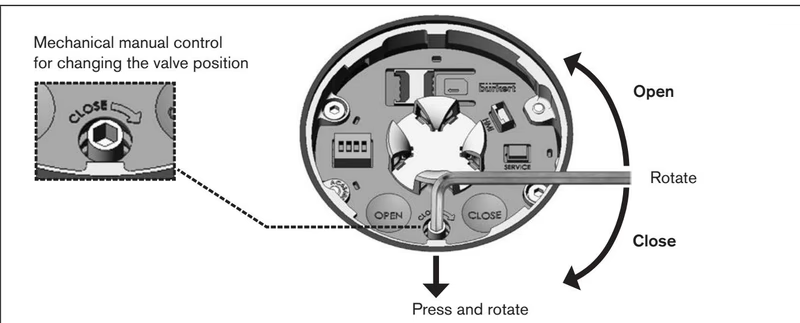
When electrical power is unavailable, manual positioning must be performed mechanically:
Mechanical Override Limitations
The mechanical manual override may be operated only in a de-energised state. Exceeding the maximum tightening torque of 2 Nm at the valve end positions will cause mechanical failure of the override assembly.
Pressure and Crush Hazard
Before opening fluid lines or detaching the actuator, depressurise and drain the pipeline. For actuators equipped with the SAFEPOS energy pack, wait until the internal capacitors discharge completely and the LED ring turns off.
Valve Position During Disassembly
The valve must be driven to at least 1/3 open before unscrewing the actuator from the valve body. Attempting to unscrew the actuator while the control cone is seated against the valve seat will permanently damage the seat contour and spindle assembly.
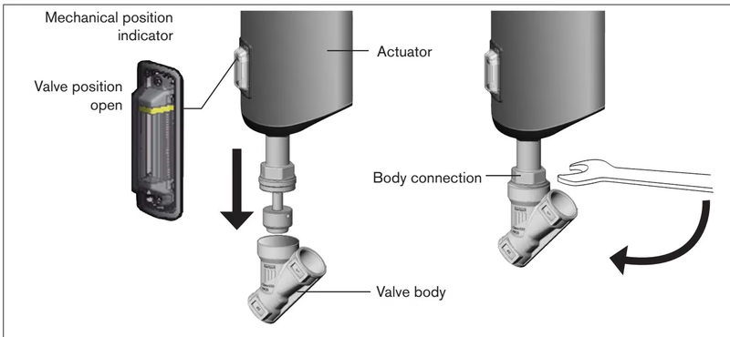
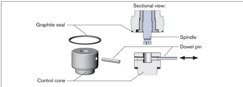
When remounting the actuator onto the valve body, fit a new graphite seal (Figure 21) and lubricate the body connection external threads with Klüberpaste UH1 96-402 (or an oxygen-approved grease where applicable). Tighten the body connection using a calibrated torque wrench:
| Body Connection Size | Tightening Torque (Nm) | Tightening Torque (lbf·ft) |
|---|---|---|
| DN 10 / DN 15 (G 1/2) | 45 ±3 Nm | 33 ±2 lbf·ft |
| DN 20 | 50 ±3 Nm | 37 ±2 lbf·ft |
| DN 25 | 60 ±3 Nm | 44 ±2 lbf·ft |
| DN 32 / DN 40 | 65 ±3 Nm | 48 ±2 lbf·ft |
| DN 50 | 70 ±3 Nm | 52 ±2 lbf·ft |
Servicing the throttling trim requires the actuator to be separated from the body with the valve driven at least 1/3 open in MANUAL mode.
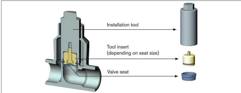
| Seat Size | Valve Body Connection | Coated Seats Torque (Nm) | Tolerance (Nm) |
|---|---|---|---|
| Seat 3 – 15 (Seat 8) | DN 10 / DN 15 | 20 Nm | +3 Nm |
| Seat 20 | DN 20 | 28 Nm | +3 Nm |
| Seat 25 | DN 25 | 40 Nm | +5 Nm |
| Seat 32 | DN 32 | 65 Nm | +5 Nm |
| Seat 40 | DN 40 | 85 Nm | +8 Nm |
| Seat 50 | DN 50 | 120 Nm | +8 Nm |
On DN 10 to DN 15 valves (seat sizes 3 to 10), the packing gland is accessible after separating the actuator base from the main actuator housing.
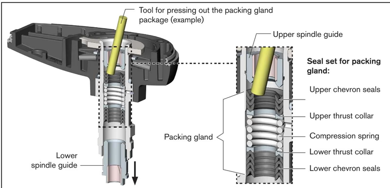
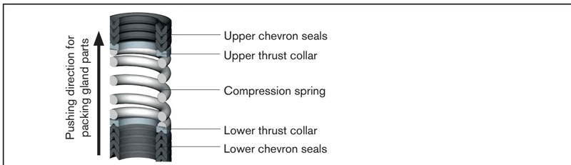
| Spindle Diameter | Valve Connection Size | Spindle Guide Tightening Torque |
|---|---|---|
| ø10 mm | DN 10 / DN 15 | 15 Nm |
| ø10 mm | DN 20 | 25 Nm |
| ø14 mm | DN 25 | 25 Nm |
| ø14 mm | DN 32 to DN 50 | 60 Nm |
Uncontrolled Actuation Risk
Never run the X.TUNE calibration function while the valve is under process media pressure. Calibrating against line pressure causes incorrect stroke reference points, leading to improper shutoff and uncontrolled process deviations.
The automatic X.TUNE calibration routine adapts the position controller to the mechanical end stops and stroke travel of the newly installed seat and cone trim.
CONFIGURATION → Position Controller → MAINTENANCE → CALIBRATION → X.TUNE. Confirm the installed seat seal material, then select start.| Cancellation Message | Cause / Corrective Action |
|---|---|
| There are device errors. | An active system fault is preventing the calibration routine from starting. |
| Time limit exceeded | Mechanical movement exceeded maximum allowed run time. Inspect spindle for binding. |
| Motor current is too high. | Actuator encountered excessive mechanical resistance during stroke travel. |
| Lower end position not detected. | Position sensor failed to detect the closed seat contact limit. Check cone seating. |
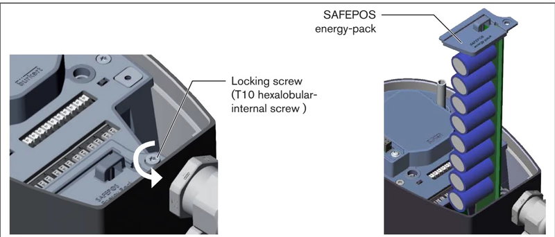
The SAFEPOS energy-pack (part number 285834) provides emergency fail-close capability when power fails.
| Item | Description / Configuration | Order Number |
|---|---|---|
| Operating Voltage Cable | M12 socket, 4-pole, length 5 m | 918 038 |
| I/O Signal Cable | M12 socket, 8-pole, length 2 m | 919 061 |
| Process Value Cable | M12 circular plug, 5-pole, length 2 m | 559 177 |
| USB büS Interface Set 1 | büS stick set 1 (power supply, stick, terminating resistor, Y-distributor, 0.7 m M12) | 772 426 |
| USB büS Interface Set 2 | büS stick set 2 (stick, terminating resistor, Y-distributor, 0.7 m M12) | 772 551 |
| büS Micro USB Adapter | M12 to büS Service interface micro USB | 773 254 |
| büS Extension Cable 1 m | M12 plug to M12 socket, 1 m length | 772 404 |
| büS Extension Cable 3 m | M12 plug to M12 socket, 3 m length | 772 405 |
| büS Extension Cable 5 m | M12 plug to M12 socket, 5 m length | 772 406 |
| büS Extension Cable 10 m | M12 plug to M12 socket, 10 m length | 772 407 |
| SIM Card | Actuator parameter storage card | 291 773 |
Explore similar products in our catalog


