IP66/67

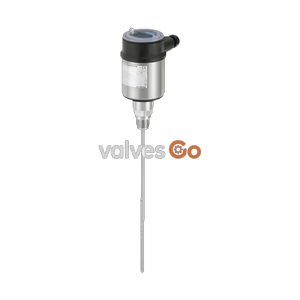
BURKERT 574562 (Type 8189) guided microwave level transmitter with 2000 mm stainless steel rod probe, Clamp DN 40 ISO 2852 connection, 4-20 mA HART output, IP66/IP67 rating, and EPDM food-grade seals.
BURKERT 574562 is a sanitary-variant Type 8189 guided microwave level transmitter equipped with a 2000 mm stainless steel rod probe and an ISO 2852 Clamp DN 40 process connection. Designed for continuous liquid level measurement, the instrument operates on time domain reflectometry (TDR) principles, sending high-frequency microwave pulses along an 8 mm diameter rod. The physical measurement is independent of steam generation, vessel pressure variations, liquid density fluctuations, condensation, and medium buildup on the probe or vessel walls.
Built specifically for hygienic processing in food, beverage, and pharmaceutical facilities, article 574562 features a wetted 316L (1.4435) stainless steel rod polished to Ra ≤ 0.76 µm with low delta ferrite content. The process seal is executed in food-quality EPDM, compliant with FDA Code of Federal Regulations requirements, and accompanied by an EN 10204 3.1 manufacturer inspection certificate. A local full dot-matrix LCD display and configuration module is included directly inside the PBT housing beneath a transparent polycarbonate cover.

| Specification Parameter | Value |
|---|---|
| Article Number | 574562 |
| Device Type | Type 8189 |
| Operating Principle | Guided microwave (TDR) |
| Probe Configuration | Interchangeable rod Ø 8 mm |
| Probe Length | 2000 mm (2.0 m) |
| Lateral Load Capacity | 10 Nm |
| Surface Roughness | Ra ≤ 0.76 µm |
| Process Connection | Clamp DN 40 (ISO 2852, collar Ø 50.5 mm) |
| Operating Voltage ($U_n$) | 16...35 V DC (with display/configuration module) |
| Analogue Output | 4...20 mA / HART (2-wire), range 3.8...20.5 mA |
| Signal Resolution | 0.3 µA |
| Fault Signal Current | Adjustable: last valid value, ≥ 21 mA, or ≤ 3.6 mA |
| Measurement Deviation | ±2 mm (DIN EN 60770-1) |
| Repeatability | ≤ ±1 mm |
| Step Response Time | ≤ 3 s (IEC 61298-2) |
| Measuring Cycle Time | < 500 ms |
| Process Pressure | -1...16 bar (-100...1600 kPa) |
| Process Temperature | -20...+130 °C (sterilisation up to +150 °C for max. 120 min) |
| Ambient Operating Temperature | -40...+80 °C |
| Ingress Protection | IP66 / IP67 (IEC/EN 60529) |
| Dielectric Constant | εr ≥ 1.6 |
Article 574562 is equipped with an ISO 2852 Clamp connection. The pipe standard specification defines an outer diameter of 38.6 mm, an inner diameter of 35.6 mm, a wall thickness of 1.5 mm, and a clamp flange collar diameter (Ø W) of 50.5 mm.
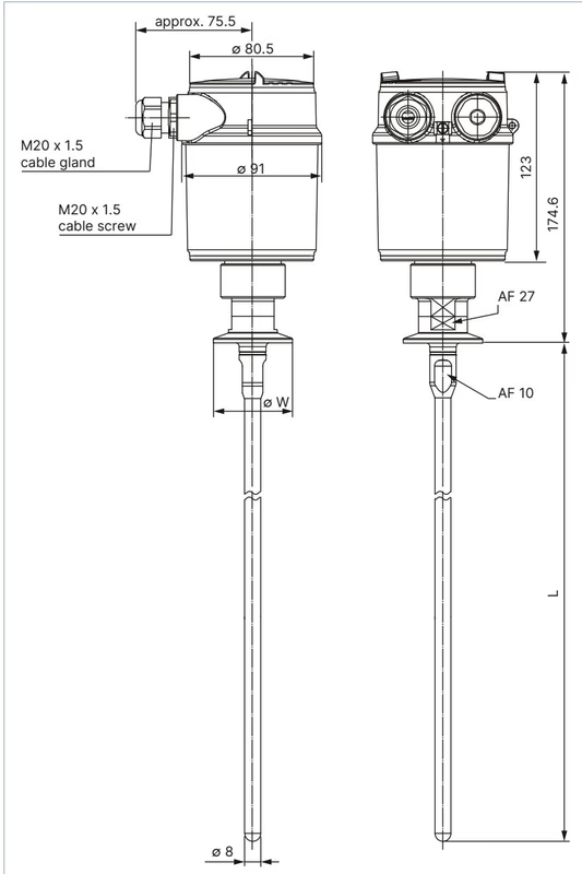
| Clamp Connection Size | Collar Diameter Ø W (mm) | Probe Length L (m) |
|---|---|---|
| 1", 1 ½" (including ISO 2852 DN 40) | 50.5 | 0.3...4 m (2.0 m for 574562) |
| 2" | 64.0 | 0.3...4 m |
| 2 ½" | 77.5 | 0.3...4 m |
| 3" | 91.0 | 0.3...4 m |
| Component Part | Material Designation |
|---|---|
| Rod probe (wetted) | Stainless steel 316L (1.4435), polished Ra ≤ 0.76 µm |
| Process fitting (wetted) | Stainless steel 316L (1.4435) / PEEK |
| Process seal (wetted) | EPDM (food quality, FDA compliant) |
| Housing body | PBT (Polyester) and stainless steel 316L (1.4404) |
| Housing cover | Polycarbonate (PC transparent) |
| Housing cover seal | EPDM |
| Cable gland / Blind plug | Polyamide (PA) / NBR seal |
| Ground terminal and screw | Stainless steel 316L |
The reference plane for measurement is the sealing surface of the clamp connection collar. Dead bands (blocking distances) exist directly beneath the reference plane and at the lower probe tip where reflection evaluation is restricted.
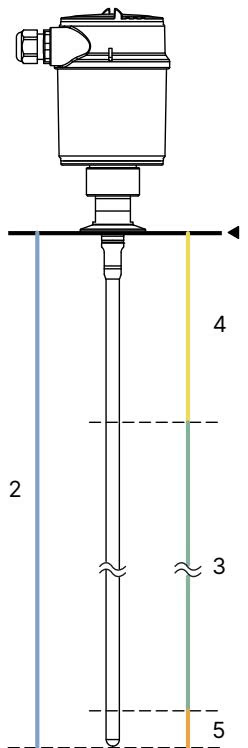
| Diagram Reference | Functional Zone | Behavior in Water | Behavior in Oil |
|---|---|---|---|
| 1 | Reference plane | Process seal surface | Process seal surface |
| 2 | Probe length | 2000 mm (for 574562) | 2000 mm (for 574562) |
| 3 | Active measuring range | 0.08...2.0 m | 0.15...1.90 m |
| 4 | Upper blocking distance | 80 mm (0.08 m) | 150 mm (0.15 m) |
| 5 | Lower blocking distance | 0 mm (0.0 m) | 100 mm (0.10 m) |
Blocking Distance Optimization
The upper blocking distance represents the minimum distance between the product surface and the reference plane. Measurements cannot be made within this zone. Activating false signal suppression in the setup menu optimizes blocking boundary transitions.
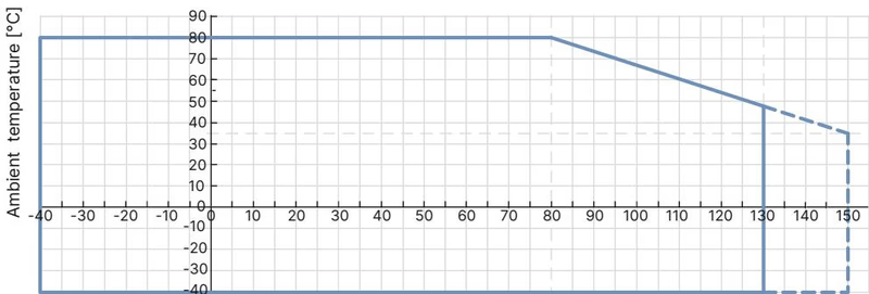
Permissible ambient operating temperatures depend directly on the process medium temperature inside the tank. Article 574562 maintains full specification up to +80 °C ambient temperature across standard process conditions.
Proper probe clearance from vessel hardware ensures accurate echo detection without phantom signals:
Vessel Nozzle Geometry
Avoid high nozzles whenever possible. If nozzles cannot be avoided, select short nozzles with small diameters and run a false signal suppression routine after mechanical mounting is complete.
Welding Precaution
Remove the electronic insert from the transmitter housing prior to carrying out any electric welding on the tank. Failure to do so exposes internal electronics to destructive inductive currents.
BURKERT 574562 operates as a 2-wire loop-powered device. Supply voltage and the 4-20 mA / HART signal are carried over the same two-conductor cable.
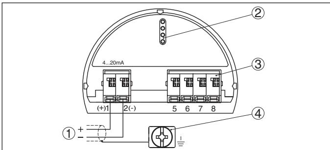
| Terminal Reference | Designation | Connection Function |
|---|---|---|
| 1 | (+) | 16...35 V DC operating power supply / signal (+) |
| 2 | (-) | Signal return / power ground (-) |
| 3 | Pins | Interface connector for display/configuration module |
| 4 | Terminal | Internal ground terminal for cable shield |
Article 574562 includes an integrated full dot-matrix LCD display and configuration module. It can be engaged or detached under power without interrupting transmitter loop operation.
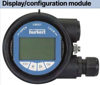
[OK] (enter/confirm), [->] (select field/shift position), [+] (change value), [ESC] (abort/step back).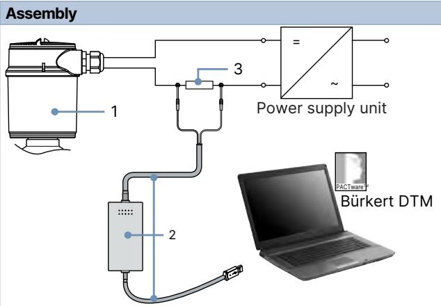
Remote configuration requires a Windows PC running PACTware with the Type 8189 Device Type Manager (DTM), connected across a 250 Ω communication resistor via a HART-USB modem (article 560177). Parameters can be saved to disk, uploaded to replacement modules, or printed for validation.
Linearization Curves
When applying pre-programmed linearization curves (horizontal cylinders or spherical tanks) to output volume units, the output current becomes proportional to volume rather than physical liquid level. Re-evaluate downstream safety trip setpoints accordingly.
Self-monitoring complies with NAMUR NE 107 and VDI/VDE 2650. The transmitter categorizes internal conditions into four distinct diagnostic states:
| Status Category | NE 107 Code | Default State | Typical Instrument Cause |
|---|---|---|---|
| Failure | F | Permanently active | Hardware defect (F040), probe breakage (F041), missing echo (F013) |
| Function Check | C | Activatable | Simulation mode active (C700) |
| Out of Specification | S | Activatable | Electronics temperature out of range (S600), overfill detected (S601) |
| Maintenance Required | M | Activatable | Low measurement certainty / echo-to-noise ratio low (M503), no echo (M505) |
Internal diagnostic memories preserve up to 100,000 measured values in a ring buffer, 500 non-deletable timestamped events, and baseline setup echo curves for long-term health tracking.
| Accessory Description | Article Number |
|---|---|
| HART-USB Modem | 560177 |
| Replacement display/configuration module kit (module, transparent cover, seal) | 559279 |
| Transparent cover replacement set with sealing ring | 561006 |
| Adapter set 2x M20 × 1.5 to ½" NPT with flat seals and blind plugs | 551782 |
Explore similar products in our catalog