Skip to content
Genuine PartsComplete Rebuild KitFor 25P Valve

Spirax Sarco 25P Main Valve Rebuild Kit

Spirax Sarco 25P Main Valve Rebuild Kit for ½" to 6" valve sizes. Includes complete set of spare parts: valve head, seat, diaphragms, spring, gaskets, bolts, screen. Restores valve performance and extends equipment life. Complies with IM-P717-04-US specifications.

Spirax Sarco 25P Main Valve Rebuild Kit

Product Overview

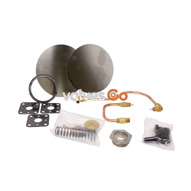
Spirax Sarco 25P Main Valve Rebuild Kit is a factory-original spare parts set designed for maintenance and overhaul of the 25P pressure reducing valve in industrial steam systems. The kit contains all critical components needed for valve maintenance, ensuring valve performance is restored to like-new condition and extending equipment service life.

Valve Sizes

½" to 6" (DN15 – DN150)
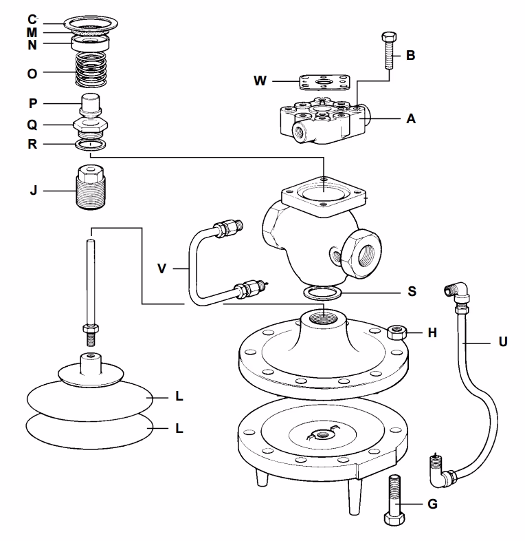
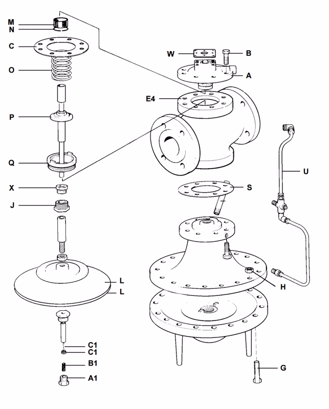
Kit Contents

½" to 2" Valve Rebuild Kit Components

ItemDescriptionQuantity
BBolts4
CGasket cap1
LDiaphragm2
MScreen1
OValve spring1
PType 25 valve head1
QType 25 valve seat1
RSeat gasket1
U, VTransmission tubing1
WPilot gasket3

Spirax Sarco 25P ½" to 2" Spare Parts Drawing

2½" to 4" Valve Rebuild Kit Components

ItemDescriptionQuantity
BBolts4
CGasket cap1
LDiaphragm2
MScreen1
OValve spring1
PType 25 valve head1
QType 25 valve seat1
RSeat gasket1
U, VTransmission tubing1
WPilot gasket3

Spirax Sarco 25P 2½" to 4" Spare Parts Drawing

6" Valve Rebuild Kit Components

ItemDescriptionQuantity
BBolts4
CGasket cap1
LDiaphragm2
MScreen1
OValve spring1
PType 25 valve head1
QType 25 valve seat1
RSeat gasket1
U, VTransmission tubing1
WPilot gasket3

Spirax Sarco 25P 6" Spare Parts Drawing

Component Information

All components are manufactured to original Spirax Sarco quality standards, ensuring complete compatibility with original parts.

Installation and Maintenance Instructions

Reference Documents

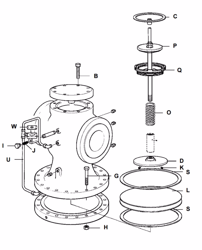
For valve cross-section drawings and additional procedure illustrations, refer to IM-P717-06-US (Figures 6, 7, and 8).

Inspecting and Replacing Main Valve Head and Seat (½" to 4")

  1. Unscrew copper tubings at (J) and (L).
  2. Disconnect pressure control line at the pressure pilot connection.
  3. Remove main valve cover cap screws (1A).
  4. Remove main valve cover, strainer, screen, and head spring.
  5. Head can then be removed by simply withdrawing with a pliers or similar tool.
  6. Inspection should then be made to determine if scale or other foreign material prevented tight closure of the head and seat.
  7. If the head or seat shows signs of wear, this can be corrected by grinding, using a fine grinding compound (400 grit) providing the wear is not too severe. Check for body erosion.
  8. If it is necessary to replace the valve seat, this can be removed from the valve body using a standard hexagon socket (Valve sizes ½" to 2"). When replacing the valve seat, a new gasket should be used to insure a tight joint. 2½" to 6" valves contain raised lugs for removal and seal metal-to-metal without a gasket.

Important

Replacement heads and seats should be lapped in to ensure proper sealing.

Inspecting and Replacing Main Valve Diaphragms (½" to 4)

  1. Unscrew copper tubing connection at (G).
  2. Remove main valve diaphragm bolts (1C).
  3. This will allow the lower diaphragm case to be removed.
  4. The 2 metal diaphragms (1H) should be inspected to insure that they have not become distorted or possibly fractured as a result of abnormal operating conditions.
  5. At the same time, any accumulation of dirt or foreign material should be removed from the diaphragm case.
  6. The valve stem (1F) should also be checked to make sure it is free to move and that there is no scale or foreign material lodged in the guide bushing.
  7. Before reassembling diaphragms in ½" to 4" sizes, main valve head must be in place and held in a closed position with the return spring and main valve cover.
  8. Make certain pressure plate (1G) is set properly (Refer to Figure 8 on IM-P717-06-US).
  9. Care should be taken in centering the diaphragms properly and equalizing bolt take-up uniformly.

Professional Tip

When reassembling, tighten bolts in a diagonal sequence to ensure even diaphragm loading.

6" Valve – Diaphragm, Seat, and Head Assembly

  1. Unscrew copper tubing connections (G) to lower diaphragm chamber.
  2. Remove main valve diaphragm bolts (1C) and drop lower diaphragm case.
  3. The 2 metal diaphragms (1H) should be inspected and replaced if they have become distorted or fractured.
  4. Clean any accumulation of dirt from the diaphragm case and orient the valve correctly for reassembly.
  5. Reassemble in the reverse order of disassembly, ensuring all components are properly seated and aligned.
  6. Tighten diaphragm bolts evenly in a diagonal pattern to ensure uniform loading on the diaphragms.

Valve Head and Seat Replacement (6" Valve)

For inspecting and replacing the 6" valve head and seat assembly, refer to the procedures outlined in the ½" to 4" section above, adapted for the larger valve body. The 6" valve contains raised lugs for seat removal and seals metal-to-metal without a gasket.