Repairable

The TLV LEX3N-TZ is an inline repairable temperature control steam trap featuring a built-in scale removal function for accurate control of condensate discharge temperatures up to 4.6 MPaG.
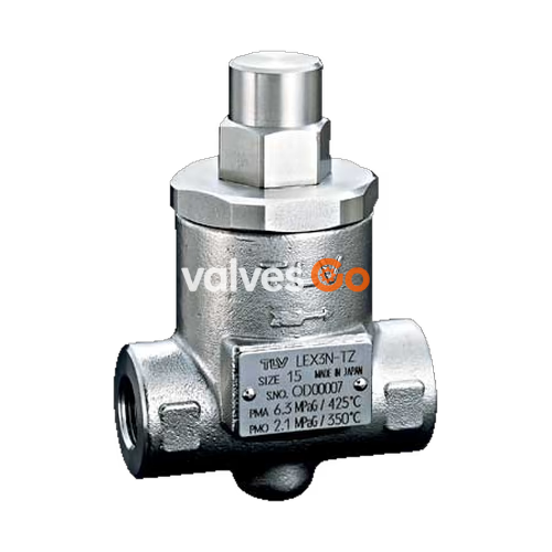
The TLV LEX3N-TZ inline repairable temperature control steam trap features a built-in scale removal function suitable for the accurate control of condensate discharge temperatures. It is designed for applications with operating pressures up to 4.6 MPaG (650 psig). Note that the LEX3N-TZ can only control the temperature of condensate discharge from the trap; it cannot control product temperature nor the temperature of condensate backing up in the system.
WARNING
Install properly and DO NOT use this product outside the recommended operating pressure, temperature, and other specification ranges. Improper use may result in such hazards as damage to the product or malfunctions, which may lead to serious accidents.
WARNING
Take measures to prevent people from coming into direct contact with product outlets. Always wear heat-insulated gloves when handling products with high body temperatures.
WARNING
When disassembling or removing the product, wait until the internal pressure equals atmospheric pressure and the surface of the product has cooled to room temperature.
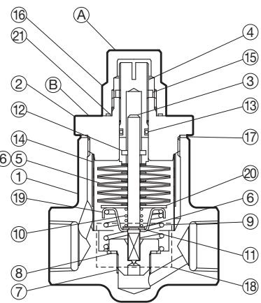
| No. | Description | No. | Description |
|---|---|---|---|
| 1 | Body | 12 | Spring Pin |
| 2 | Cover | 13 | Seal Ring |
| 3 | Valve Stem | 14 | Screen |
| 4 | Adjusting Screw | 15 | Locknut |
| 5 | Bimetal Element | 16 | Cap Nut |
| 6 | Washer | 17 | Cover Gasket |
| 7 | Valve Seat | 18 | Nameplate |
| 11 | Snap Ring | 21 | Cap Nut Gasket |
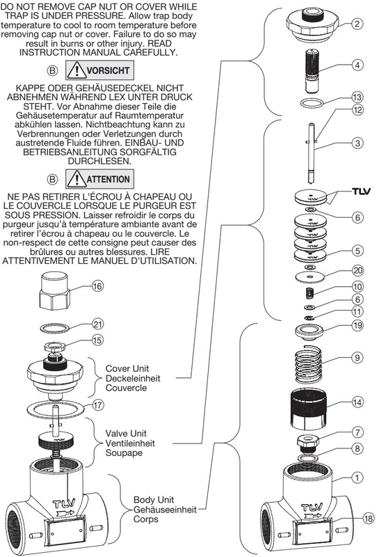
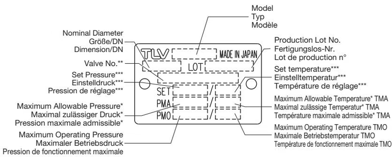
INFO
Maximum allowable pressure (PMA) and maximum allowable temperature (TMA) are PRESSURE SHELL DESIGN CONDITIONS, NOT OPERATING CONDITIONS.
| Status | Visual Symptoms |
|---|---|
| Normal | Condensate is being discharged from the discharge outlet. (The surface temperature of the trap should be about 10 to 20 °C lower than the set temperature.) |
| Blocked | No condensate is discharged and the surface temperature of the trap is low. |
| Blowing | Live steam continually flows from the outlet and there is a continuous hissing sound of flow. The surface temperature of the trap is higher than the set temperature. |
WARNING
To prevent possible injury, always relieve pressure from trap before opening to adjust the temperature setting. Always wear heat-insulated gloves and eye protection.
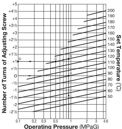
The standard "0" position is where the bottom of the adjusting screw slot is even with the top surface of the cap.
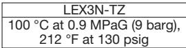
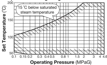
The trap can be set to open at any temperature between 50 °C and 200 °C provided the set temperature is at least 15 °C below saturated steam temperature.
The LEX3N-TZ contains a built-in cleaning device that can be used without removing the trap from the line to remove rust, scale, and buildup from the valve seat.
Operational inspections should be performed at least twice per year.
| Part | Parts Inspection Procedure |
|---|---|
| Gasket(s) | Check for warping and damage |
| Seal Ring | Check for scratches and wear |
| Valve Stem | Check for scratches and wear |
| Bimetal Element | Check for wear and deformation |
| Springs | Check for wear on over-expansion and return springs |
| Screen | Check for clogging, corrosion or damage |
| Valve Seat | Check for rust, scale, oil film wear or damage |
| Body, Cover | Check inside for rust and scale |
| Part | Torque (N·m) | Distance Across Flats (mm) |
|---|---|---|
| Cap Nut | 35 | 24 |
| Cover | 250 | 46 |
| Valve Seat | 30 | 19 |
| Problem | Cause | Remedy |
|---|---|---|
| No condensate is discharged or temperature doesn't rise | Bimetal element damaged or broken | Replace with new bimetal element |
| Assembly of bimetal elements is incorrect | Correct the assembly | |
| Build-up of foreign matter between elements | Clean the bimetal elements | |
| Valve seat or screen clogged with rust and scale | Use cleaning function or clean parts | |
| Adjusting screw not correctly positioned | Readjust the screw | |
| Steam is blowing or temperature rises above set point | Dirt or scale on valve stem or seating surfaces | Use cleaning function |
| Valve stem or seat is worn or damaged | Replace with new valve stem/seat | |
| Valve seat is loose | Tighten to the proper torque | |
| Valve seat gasket is damaged | Replace with a new gasket | |
| Steam leakage from trap exterior | Cap nut gasket, seal ring, or cover gasket damaged | Replace with new gasket or seal ring |
Explore similar products in our catalog