3450 RPM Motors

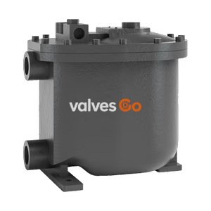
The Armstrong PT-104 Mini Pump Trap is a compact, non-electric solution for returning condensate from low points. Features a cast iron body and max 100 psig operating pressure.
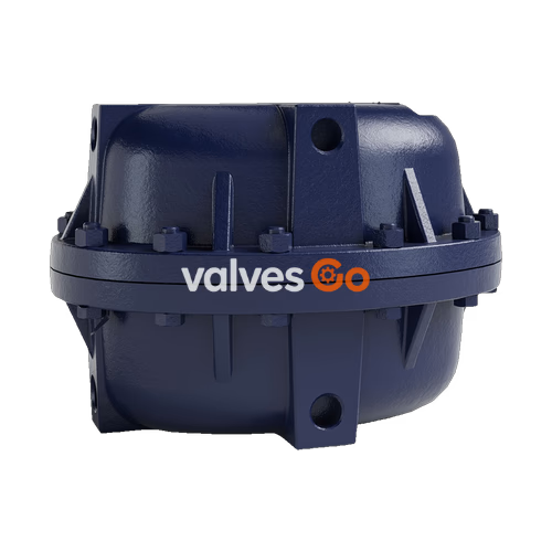
The Armstrong PT-104 Mini Pump Trap is the smallest non-electric solution that can move condensate or other liquids from lower to higher points and from lower to higher pressures. Condensate can be returned at temperatures well above the 210°F limit of conventional electric centrifugal pumps without the headaches of leaking seals or cavitation problems. The PT-104 Mini Pump Trap is a small solution for a big problem, designed to fit in tight space requirements while allowing minimal fill head.

| Connection | Type | in | mm |
|---|---|---|---|
| Inlet | NPT | 1 | 25 |
| Outlet | NPT | 1 | 25 |
| Vent | NPT | 1/2 | 15 |
| Motive Pressure | NPT | 1/2 | 15 |
| Optional Gauge Glass | NPT | 1 | 25 |
| Optional Cycle Counter | NPT | 1 | 25 |
| Name of Part | Material |
|---|---|
| Body and Cap | Cast Iron ASTM A48 cl.30 |
| Vent/Inlet Valves | Stainless Steel |
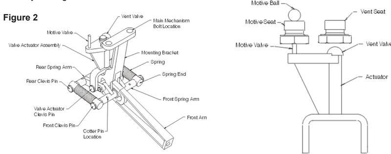
| Mechanism Assembly | Stainless Steel |
| Spring | Inconel X-750 |
| Gasket | Compressed non-asbestos |
| Bolts | SA 449 |
| Nuts | ASTM A194 Gr.2H |
| Plug | Cast Iron |
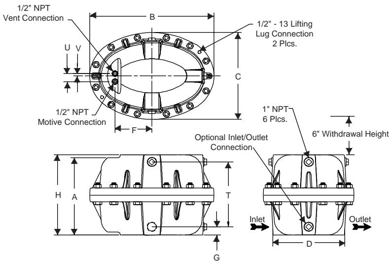
| Dimension | in | mm |
|---|---|---|
| A | 12 | 305 |
| B | 18-1/2 | 470 |
| C | 13-1/2 | 343 |
| D | 10-3/4 | 272 |
| F | 5-1/2 | 140 |
| G | 1-5/16 | 33 |
| H | 12-1/2 | 317 |
| U | 1-1/4 | 32 |
| V | 3/8 | 9 |
| T | 10-1/16 | 256 |
| Weight lb (kg) | 169 | (77) |
| Bronze Check Valves lb (kg) | 4 | (2) |
| Stainless Steel Check Valve lb (kg) | 4 | (2) |
| Maximum Operating Pressure | 100 psig (7 bar) | |
| Maximum Allowable Pressure | 150 psig (10 bar) @ 450°F (232°C) |
Note on Motive Pressure
Although the maximum operating pressure is 100 psi (7 bar), it is highly recommended that the motive be set only 15 - 20 psi (1.0 - 1.4 bar) above the discharge pressure. For applications with greater than 18" of filling head or condensate temperature less than 185°F, it is recommended that the motive pressure be set 25-35 psi above the backpressure. Air is the preferred motive for condensate temperatures less than 180°F (82°C).
Filling Head: Install the pumping trap below the equipment being drained. A recommended filling head of 6" (152 mm) is recommended for the Model PT-104. Filling head is the distance between the bottom of a vented receiver or reservoir pipe and the top of the pumping trap cap. Greater fill heads increase the capacity of the pump trap; however, it is not recommended to have a filling head greater than 24 inches.
Liquid Reservoir: Liquid flowing from the equipment being drained must be stored during the pump’s discharge cycle. A liquid reservoir (pipe reservoir) or vented receiver should be installed in a horizontal plane to prevent flooding of equipment.
Check Valves Required
The pumping trap will not function without inlet and discharge check valves. Connect the Armstrong supplied check valves to the pump. The swing check is the inlet check valve and the spring assisted valve is used at the pump discharge.
Motive Inlet Piping: Connect the motive force piping (steam, air or inert gas) to the inlet connection on the pump cap. Proper piping and trapping of the motive supply line must include a strainer, check valve, properly sized drip leg with mud pocket, and drip trap (for steam motive). A pressure reducing valve must be used when the motive pressure exceeds 100 psi (7 bar).
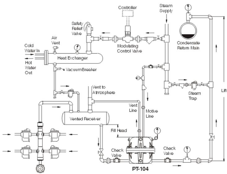
Pumping of condensate from vented receiver handling single or multiple steam trap discharges. Motive force of steam is depicted.
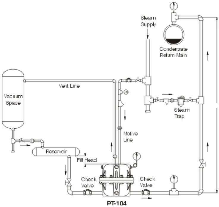
Draining liquid from equipment under vacuum. The Pumping Trap provides drainage assistance whether liquid discharge is to gravity or overhead.
Explore similar products in our catalog