Transit-Time Ultrasonic

Armstrong VERIS Verabar® averaging pitot flow sensor features a solid one-piece bullet shape for clog-free, highly accurate gas, liquid, and steam measurement.
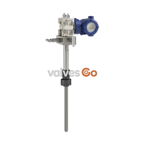
Armstrong VERIS Verabar® averaging pitot flow sensor provides unsurpassed accuracy and reliability for measuring gas, liquid, and steam. Developed from aerospace technology, the Verabar® features a solid one-piece construction and a unique bullet shape that makes flow measurement clog-free and precise. The aerodynamic shape reduces drag and flow-induced vibration, ensuring long-term structural integrity and stable signal output.

When fluid impacts the sensor, it creates a high-pressure zone at the front. As the fluid accelerates around the sensor, it creates a low-pressure zone at the sides and rear. The Verabar® averages the velocity profile through multi-sensing ports that span the entire pipe diameter.
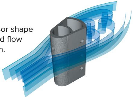
Clogging typically occurs in low-pressure ports located in or near the partial vacuum at the rear of a sensor. The Verabar® design locates the low-pressure ports on the sides of the sensor, forward of the fluid separation point and turbulent wake area. This virtually eliminates clogging and produces an extremely stable signal.
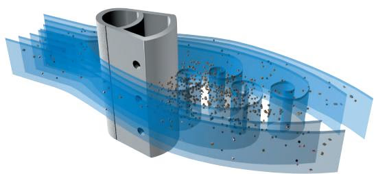
The grooves and roughness on the Verabar’s frontal surface relieve the partial vacuum at the rear of the sensor, reducing pressure drag. This extends the accuracy and rangeability to very low velocities. The sensor maintains an accuracy of ±1% of flow rate, and up to ±0.5% if calibrated.
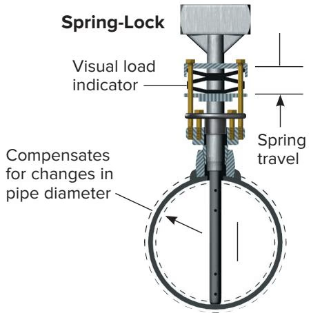
This advanced, patented design ensures the sensor remains sealed, locked, and pre-loaded to the opposite wall regardless of changes in pipe diameter due to pressure, temperature, or mechanical force.
Designed specifically for high-velocity cooling water applications, large diameter pipes, large vertical stacks, and buried water lines. The partial insert extends 1/3 into the pipe to reduce procurement and installation costs, and can be inserted/retracted with no reduction in flow rate.
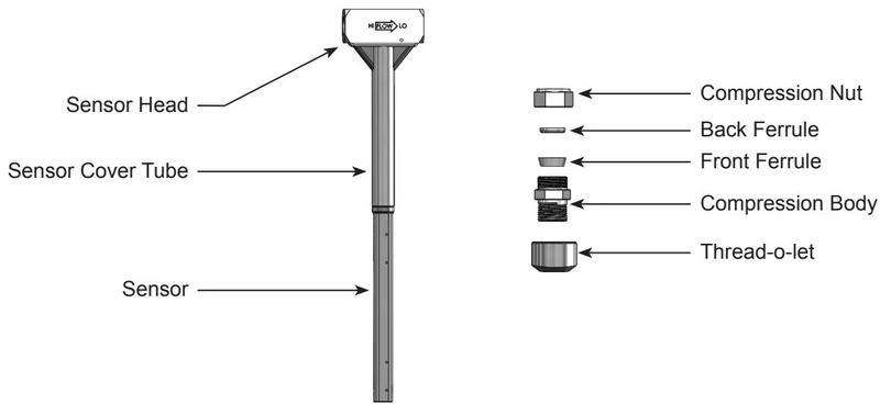
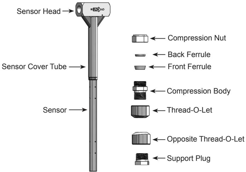
The most cost-effective models, featuring mounting through a tube fitting. The V100 is a single support design, while the V110 includes additional support on the opposite wall of the pipe. Suitable for low and medium pressures.
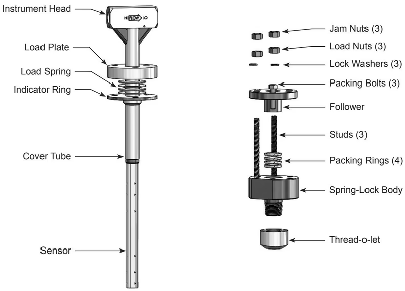
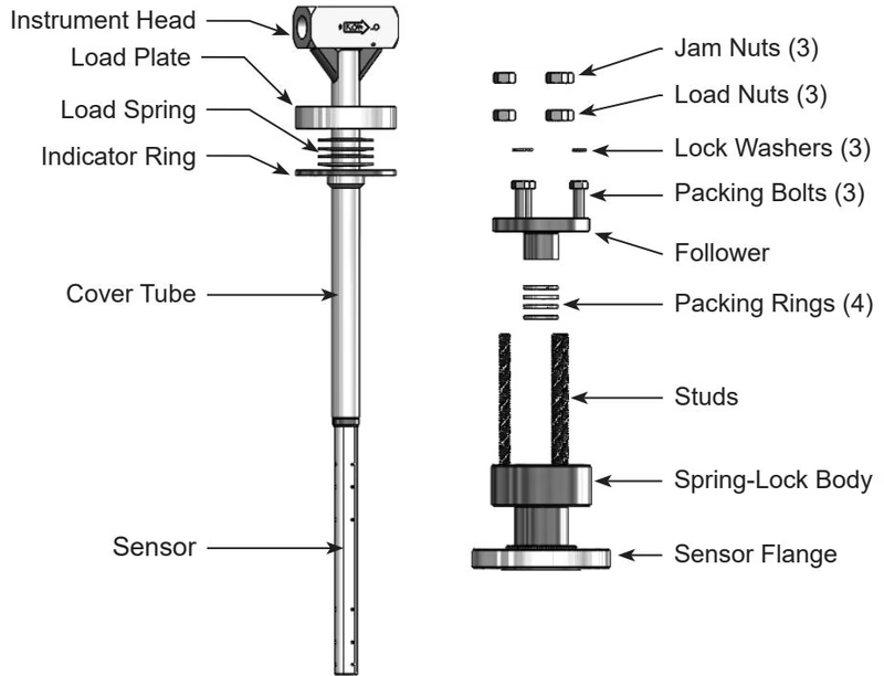
Features threaded mounting components and the Spring-Lock feature that pre-loads the sensor to the opposite pipe wall. It is blow-out and leak resistant, compensating for changes in pipe diameter.
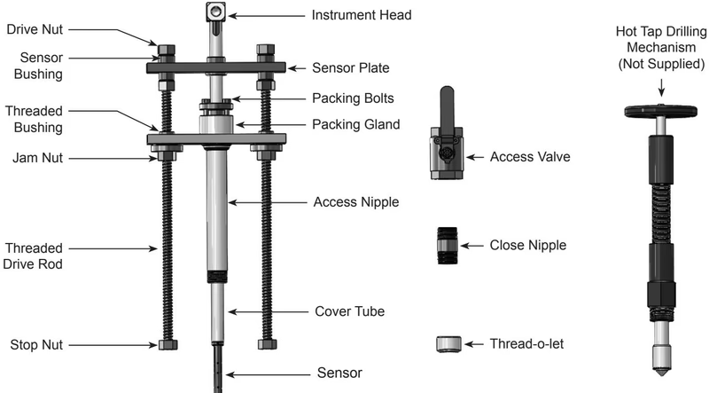
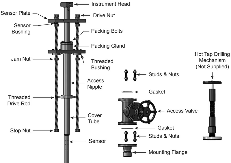
Can be inserted and removed from service under pressure without system shutdown. The V200S features a single drive rod, while the V200D features double drive rods for higher pressures (up to 600# max).
Similar to the V200 series but utilizes flanged mounting components (flanged ball or gate access valves). Available in single rod (V400S) and double rod (V400D) configurations.
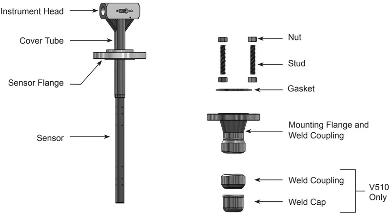
Features an all-welded flanged mounting, preferred in power, petrochemical, and refining industries. The V500 is a single support model, and the V510 includes additional support on the opposite wall. Capable of handling high pressures up to ANSI Class 2500#.
Combines flanged mounting components with the Spring-Lock feature, ensuring the sensor remains sealed and pre-loaded to the opposite pipe wall under varying conditions.
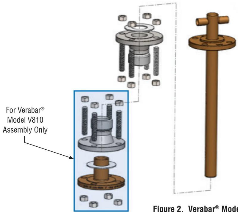
The special round-bar design of the V800 and V810 models is constructed of Ni-Al-Br and specifically designed for use in sea water applications. The V800 features flanged mounting, and the V810 includes opposite wall support.
Safety Precautions
Check the maximum operating conditions on the flow sensor nameplate. Verify that the maximum operating conditions of the application do not exceed the parameters stated on the nameplate. Ensure the pipe is depressurized and drained prior to installation (unless using Hot Tap models).
For the most accurate flow measurement, a minimum straight run of pipe is required. If longer straight runs are available, position the Verabar® such that the ratio of upstream straight run to downstream straight run is approximately 4 to 1.
| Upstream Disturbance | Minimum Upstream (D) | Minimum Downstream (D) |
|---|---|---|
| Single 90° Elbow or T-fitting | 7 | 3 |
| Two 90° Elbows in same plane | 9 | 3 |
| Two 90° Elbows in different planes | 19 | 3 |
| Reducer / Expander | 8 | 3 |
| Gate Valve (fully open) | 8 | 3 |
| Globe or Control Valve | 24 | 3 |
(Note: D = Pipe Diameters. Straightening vanes should be positioned such that the end closest to the Verabar® is halfway between the Verabar® and the closest upstream configuration.)
Explore similar products in our catalog