


Up to 99.8% Efficiency

BURKERT 20007990 (Type 3361) is an electromotive 2-way globe control valve with DN 32 DIN EN 1092-1 PN 25 flange, stainless steel body, AG2 2500 N actuator, display, SAFEPOS fail-safe energy pack, and Kvs 17.8 m³/h.
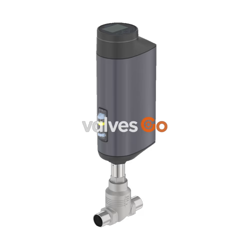
BURKERT 20007990 (Type 3361) is an electromotive 2-way globe control valve engineered for continuous process throttling under demanding industrial conditions. Configured with a DN 32 DIN EN 1092-1 PN 25 flanged connection, cast CF3M stainless steel globe body, and AG2 electromotive linear actuator (2,500 N nominal driving force), this unit provides precise control across operating pressures from 0 to 25 bar(g). The internal assembly features a 32 mm seat diameter with a stainless steel 1.4571 metallic seat seal and an equal-percentage control cone (50:1 theoretical rangeability), delivering a calibrated maximum flow coefficient Kvs of 17.8 m³/h (Cv 20.8 gpm) with seat tightness compliant with DIN EN 60534-4 Class IV.
The linear drive system pairs a brushless DC motor with a precision ball screw to achieve positioning repeatability with a control dead band of ±0.1% at a linear travel speed of 4 mm/s. The integrated digital positioner processes standard analogue command signals (0/4 to 20 mA or 0 to 5/10 V) with full electrical isolation, complemented by digital inputs and outputs. A built-in display module with operating keys and a 360° LED status ring provides direct parameter configuration and visual diagnostic feedback. To prevent unmonitored line states during plant power failure, an internal SAFEPOS energy-pack capacitive storage module automatically returns the stem to a factory-set normally closed safety position.
BURKERT 20007990 operates across a medium temperature span of -10 °C to +185 °C and an ambient temperature range of -25 °C to +65 °C, subject to thermal derating curves determined by actuator electronics and internal power dissipation.
| Technical Parameter | Specification Value |
|---|---|
| Product Identification | Type 3361 (Article No. 20007990) |
| Valve Design | Electromotive 2-way globe control valve |
| Nominal Diameter (DN) | DN 32 (NPS 1 1/4") |
| Port Connection | Flange DIN EN 1092-1 PN 25 (Face-to-face FTF 1 acc. to DIN EN 558-1 = 180 mm) |
| Nominal Pressure Class | PN 25 (DIN EN 1333) / Class 150 (DIN EN 1759) |
| Operating Pressure Range | 0 to 25 bar(g) |
| Flow Coefficient (Kvs) | 17.8 m³/h (Cv 20.8 gpm) |
| Seat Diameter | 32 mm |
| Flow Characteristic | Equal percentage (theoretical rangeability 50:1) |
| Seat Leakage Class | Class IV acc. to DIN EN 60534-4 (0.01% of nominal flow) |
| Medium Temperature Range | -10 °C to +185 °C |
| Permissible Ambient Temperature | -25 °C to +65 °C (see thermal derating chart) |
| Supply Voltage | 24 V DC ±10% (max. residual ripple 10%) |
| Maximum Current Consumption | 3 A at max. load (includes 1 A SAFEPOS charging; +2 A at lowest operating temp) |
| Standby Power | 2 to 5 W |
| Actuator Size & Driving Force | AG2 (2,500 N nominal force) |
| Travel Speed & Closing Time | 4 mm/s; typical closing time 6.4 s (6,400 ms) |
| Duty Cycle | 100% continuous |
| Fail-Safe Energy Backup | SAFEPOS energy-pack (normally closed on power interruption) |
| Enclosure Rating | IP65 / IP67 (DIN EN 60529), NEMA 4X |
| Food Contact Compliance | EC Regulation 1935/2004 compliant per manufacturer declaration |
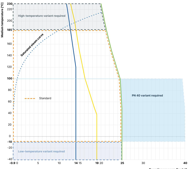
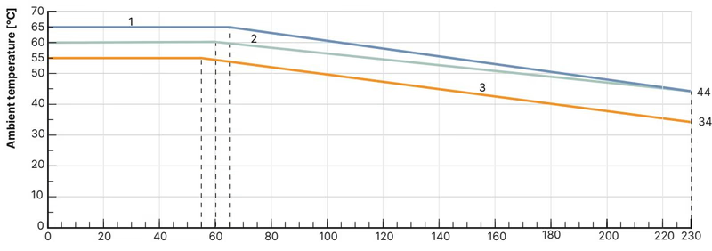
Thermal Derating Guidelines
When the valve is equipped with both the HMI display module and the SAFEPOS energy-pack (as in model 20007990), permissible ambient temperature is constrained by curve 3 of the AG2 derating diagram. At maximum medium temperatures up to +185 °C, ensure adequate enclosure ventilation to maintain ambient air below the corresponding curve ceiling.
The wetted valve body is precision investment cast in CF3M austenitic stainless steel, paired with an all-metal 1.4571 seat and control cone to resist cavitation and thermal stress.
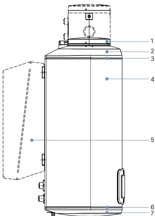
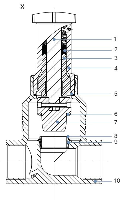
| Item | Component | Material |
|---|---|---|
| 1 | Display Housing / Blind Cover | PPS (Polyphenylene sulphide) |
| 2 | Actuator Cover | PPS |
| 3, 6 | Enclosure O-Rings & Flat Seals | EPDM |
| 4 | Actuator Housing | Die-cast aluminium, powder-coated |
| 7 | Actuator Base | PPS |
| — | Spindle | Stainless steel 1.4401 (316) / 1.4404 (316L) |
| — | Spindle Packing Gland | Filled PTFE V-rings with Belleville spring compensation |
| — | Spindle Guide | Stainless steel 1.4404 (316L) |
| — | Packing Gland Tube | Stainless steel 1.4401 (316) |
| — | Body Seal | Graphite |
| — | Seat Seal | Stainless steel 1.4571 |
| — | Control Cone & Valve Seat | Stainless steel 1.4571 |
| — | Valve Seat O-ring | EPDM or PTFE |
| — | Valve Body | Cast stainless steel CF3M (equivalent to 316L) |
Fluid flow is directed underneath the seat (flow direction 2 to 1) to eliminate water hammer and provide stable dynamic regulation across high differential pressures.
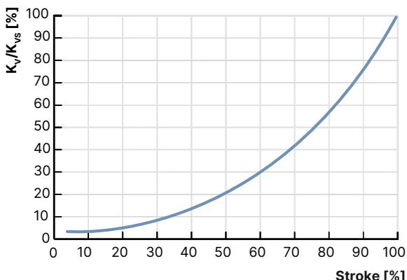
For DN 32 with a 32 mm seat diameter and 2,500 N actuator force, the certified water flow progression in m³/h at rated travel stroke increments according to DIN EN 60534-2-4 is structured as follows:
| Seat Size | Actuator Force | Differential Pressure | Theoretical Rangeability | 5% Stroke | 10% Stroke | 20% Stroke | 30% Stroke | 40% Stroke | 50% Stroke | 60% Stroke | 70% Stroke | 80% Stroke | 90% Stroke | 100% Stroke (Kvs) |
|---|---|---|---|---|---|---|---|---|---|---|---|---|---|---|
| 32 mm | 2,500 N | 25 bar(g) | 50:1 | 0.48 m³/h | 0.60 m³/h | 0.85 m³/h | 1.3 m³/h | 2.1 m³/h | 3.1 m³/h | 4.5 m³/h | 6.8 m³/h | 10.2 m³/h | 14.0 m³/h | 17.8 m³/h |
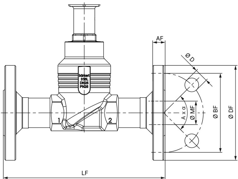
BURKERT 20007990 adheres to DIN EN 1092-1 flange standards with Face-to-Face dimensions according to DIN EN 558-1 Series 1 (180 mm).
| Dimension Property | Symbol | Metric Value (mm) |
|---|---|---|
| Face-to-face Length (DIN EN 558-1 FTF 1) | LF | 180 mm |
| Flange Outer Diameter | ∅ DF | 140 mm |
| Bolt Circle Diameter | ∅ BF | 100 mm |
| Flange Thickness | AF | 18 mm |
| Bolt Hole Diameter | ∅ D | 18 mm |
| Number of Bolt Holes & Pitch | A × α | 4 × 90° |
| Raised Face / Seat Neck Diameter | ∅ MF | 38.4 mm |
| Actuator Height (standard with display) | H1 | 474 mm |
| Actuator Stroke Clearance Extension | — | Approx. +2 mm in fully closed position |
| Actuator Total Weight (AG2) | — | 5.5 kg (excluding valve body) |
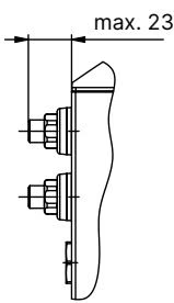
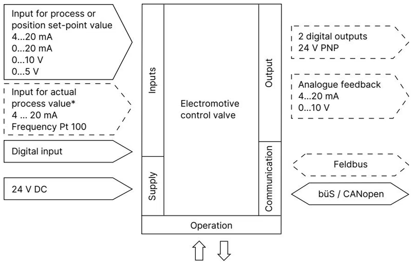
Electrical connection is realized through M12 industrial circular connectors located at the base of the AG2 actuator. Analogue control commands and feedback monitoring run through connector X1, while operating power and büS communication share connector X3.
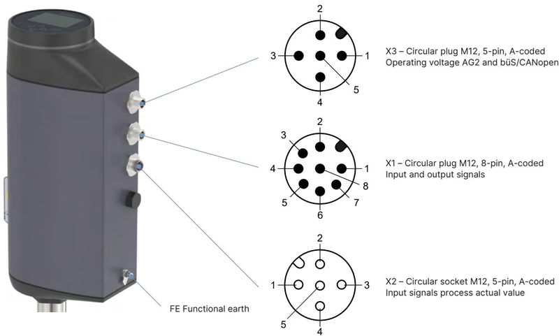
| Connector | Pin | Wire Designation / Function |
|---|---|---|
| X1 – M12 Plug, 8-pin, A-coded (Input and Output Signals) | 1 | Digital input + |
| 2 | GND for digital input and digital outputs | |
| 3 | Digital output 2 + (PNP, max. 100 mA) | |
| 4 | Digital output 1 + (PNP, max. 100 mA) | |
| 5 | Analogue output - | |
| 6 | Analogue output + (0/4..20 mA, load 0..800 Ω; or 0..5/10 V, max. 10 mA) | |
| 7 | Analogue set-point input - | |
| 8 | Analogue set-point input + (0/4..20 mA, Ri = 70 Ω; or 0..5/10 V, Ri = 22 kΩ) | |
| X3 – M12 Plug, 5-pin, A-coded (Operating Voltage & büS) | 1 | CAN Shield / functional shield |
| 2 | Operating voltage +24 V DC ±10% | |
| 3 | GND / CAN_GND | |
| 4 | CAN_H (Bürkert system bus büS) | |
| 5 | CAN_L (Bürkert system bus büS) |
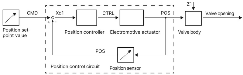
BURKERT 20007990 integrates a non-contact internal displacement transducer that constantly monitors linear valve stem position. The closed-loop controller compares the real-time position (POS) to the incoming set-point value (CMD), correcting motor drive output with zero steady-state droop.
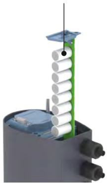
The internal SAFEPOS energy-pack module delivers backup electrical charge to power the brushless motor in the event of an external 24 V DC interruption. The factory configuration positions the valve to normally closed (NC), although intermediate safety positions can be programmed via the display menu. The storage module reaches full charge readiness within 120 seconds of initial power-up. Continuous internal self-diagnostics monitor capacitor aging over its operating life (up to 10 years) and trigger proactive warning messages on the display before end-of-life.
Mechanical Override Limit
Actuate the mechanical manual override only when the valve is completely de-energized. Do not exceed the maximum tightening torque limit of 2 Nm at the physical end stops to prevent mechanical drive gear damage.
Routine maintenance involves inspecting the relief bore for trace leakage past the primary stem seals. Replacing trim components requires strict adherence to specified tightening torques and subsequent positioner re-tuning.
| Assembly Joint / Fastener | Tool Required | Tightening Torque |
|---|---|---|
| Valve Body Connection (DN 32) | Open-end wrench | 65 ±3 Nm (48 ±2 lbf ft) |
| Valve Seat (DN 32) | Installation tool 652607 + torque wrench | 65 +5 Nm |
| Spindle Guide (ø14 mm Spindle, DN 32) | Modified socket wrench (SW21, 683223) | 60 Nm |
| Actuator Base Screws (AG2) | Screwdriver | 5 Nm crosswise |
| Actuator Cover Fasteners | Hexalobular internal key T25 | 5 Nm |
| Display Module Fastening Screws | Hexalobular internal key T20 | 1.1 Nm |
| SAFEPOS Locking Screw | Hexalobular internal key T10 | 1.1 Nm |
| Mechanical Manual Override | Allen key 3 mm | Max. 2 Nm limit |
Calibration with X.TUNE
Whenever the actuator is uncoupled from the CF3M valve body or after replacing the control cone, seat, or stem packing, run the automatic X.TUNE calibration routine. Initiate X.TUNE via the HMI display menu under CONFIGURATION > Position controller > MAINTENANCE > CALIBRATION > X.TUNE or by pressing both internal OPEN and CLOSE buttons simultaneously for 5 seconds under zero process pressure. Never execute X.TUNE under line pressure.
Explore similar products in our catalog


