

PN16

BURKERT 20011744 (Type 2875) direct-acting 2/2-way proportional solenoid control valve features G 3/8 ports, DN 3 mm orifice, stainless steel body, FKM seal, 12 V DC coil, and oxygen-cleaned construction.
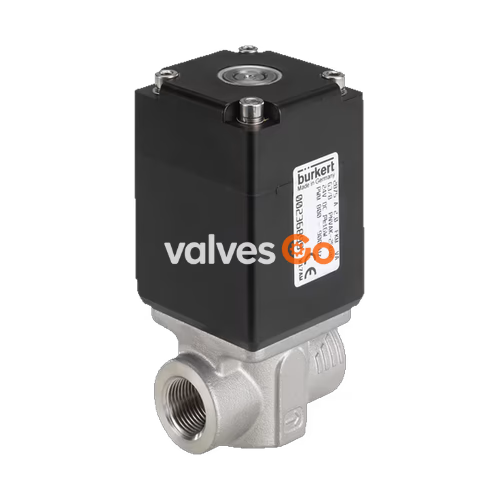
BURKERT 20011744 (Type 2875) is a direct-acting 2/2-way proportional solenoid control valve configured for closed-loop regulating circuits. Operating under circuit function A (normally closed), the valve uses an elastomeric seat seal that closes bubble-tight up to its 10 bar nominal pressure rating. The plunger assembly is supported in a frictionless suspension, eliminating mechanical stick-slip behavior and ensuring sensitive adjustment characteristics across its 1:100 operating range.
This specific article 20011744 is built with a stainless steel body, G 3/8 female threaded process ports, and a DN 3.0 mm orifice. It delivers a water flow coefficient Kv of 0.25 m³/h and a nominal air flow rate QNn of 270 l/min. Configured with a 12 V DC electromagnetic coil and FKM seals, it is specially degreased and tested for oxygen service in compliance with DIS 1000020797, making it suitable for clean gas delivery and analytical control applications.

Type 2875 valves operate as the final control element in electronic process loops and can be combined with standard Bürkert control electronics and connection hardware:
| Parameter | Specification Details |
|---|---|
| Circuit Function | Circuit function A (CF A): 2/2-way, normally closed, flow below seat |
| Actuation Principle | Direct-acting proportional plunger valve, frictionless plunger guide |
| Orifice Size (DN) | 3.0 mm |
| Port Connection | G 3/8 internal thread |
| Flow Coefficients | Kv (water): 0.25 m³/h; QNn (neutral gas): 270 l/min |
| Operating Pressure Range | -1.0 bar to 10.0 bar (gauge pressure relative to atmosphere) |
| Maximum Differential Pressure | 10.0 bar |
| Body Material | Stainless steel |
| Seal Material | FKM (fluor rubber) seat seal and outer seal |
| Operating Voltage | 12 V DC (±10%) |
| Nominal Power Consumption | 16 W |
| PWM Frequency | 400 Hz to 500 Hz (variant for higher differential pressures) |
| Positioning Behavior | Hysteresis < 5%; Repeat accuracy < 0.5% FS; Response sensitivity < 0.25% FS |
| Actuating Time (10% to 90%) | < 25 ms |
| Duty Cycle | 100% continuous operation (ED) |
| Fluid Temperature Range | -10 °C to +60 °C (extended capability -10 °C to +90 °C with FKM) |
| Ambient Temperature Range | -10 °C to +55 °C |
| Fluid Kinematic Viscosity | Max. 21 mm²/s (21 cSt) |
| Electrical Connection | Plug pattern Form A according to DIN EN 175301-803 (plug not included) |
| Ingress Protection Rating | IP65 with properly mated Type 2518 cable plug |
| Cleanliness Standard | Oxygen version, free of oil, grease, and silicone per DIS 1000020797 |
Accurate nominal diameter sizing ensures proper control stability and avoids valve saturation. The sizing must account for both sub-critical and supercritical flow regimes across the valve seat:
| Pressure Drop Regime | Kv Value for Liquids [m³/h] | Kv Value for Gases [m³/h] |
|---|---|---|
| Sub-critical ($p_2 > \frac{p_1}{2}$) | $= Q \cdot \sqrt{\frac{\rho}{1000 \cdot \Delta p}}$ | $= \frac{Q_N}{514} \cdot \sqrt{\frac{T_1 \cdot \rho_N}{p_2 \cdot \Delta p}}$ |
| Supercritical ($p_2 < \frac{p_1}{2}$) | $= Q \cdot \sqrt{\frac{\rho}{1000 \cdot \Delta p}}$ | $= \frac{Q_N}{257 \cdot p_1} \cdot \sqrt{T_1 \cdot \rho_N}$ |
Where:
Pressure Drop and Sizing
For proportional valves to maintain a linear system characteristic, the nominal diameter must be selected so that at full opening, approximately 25% of the total circuit pressure drop occurs across the valve ($\Delta p_{valve} \approx 25%$ of total $\Delta p$). If the differential pressure exceeds half the nominal pressure value, flow discontinuities may occur.
Type 2875 valves are available in threaded body and sub-base configurations. The dimensional values for standard threaded variants are tabulated below:
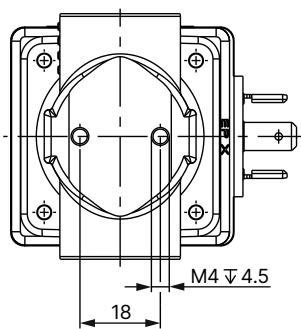
| Port Connection Size | Thread Type | Thread Depth F1/F2 [mm] | Thread Identification G1/G2 |
|---|---|---|---|
| 3/8" | G internal thread (F1, G1) | 12.0 mm | G 3/8 |
| 3/8" | NPT internal thread (F2, G2) | 10.3 mm | NPT 3/8 |
| 1/2" | G internal thread (F1, G1) | 14.0 mm | G 1/2 |
| 1/2" | NPT internal thread (F2, G2) | 13.7 mm | NPT 1/2 |
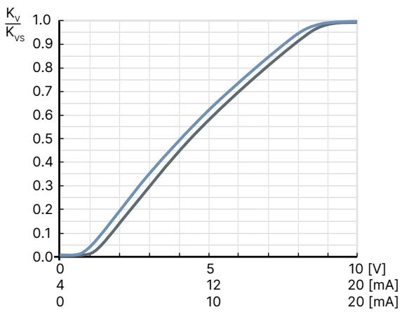
Control of Type 2875 is achieved through pulse-width modulation (PWM). The duty cycle of the PWM control signal determines the average effective coil current, which counteracts an opposing spring to set the exact plunger lift position.
Type 8605 control electronics modulate the current between the set minimum and maximum operating thresholds. When operating the higher differential pressure variant with a 12 V DC coil, a recommended PWM switching frequency of 400 Hz to 500 Hz provides stable positioning dynamics. Integrated coil temperature compensation inside Type 8605 automatically offsets coil resistance changes resulting from ohmic heating during continuous operation.
Type 2875 covers multiple orifices and pressure ratings across brass and stainless steel bodies. Article 20011744 represents the 12 V DC stainless steel execution with oxygen cleaning. The standard 24 V DC product variants for higher differential pressures are detailed below for technical cross-reference:
| Circuit Function | Port Connection | Orifice [mm] | Approvals | Kvs (Water) [m³/h] | Nominal Pressure [bar] | Article No. Brass Body | Article No. Stainless Steel Body |
|---|---|---|---|---|---|---|---|
| CF A (NC) | G 3/8 | 2.0 | None | 0.12 | 25 | 239040 | 239085 |
| CF A (NC) | G 3/8 | 2.0 | UR | 0.12 | 25 | 275000 | 275005 |
| CF A (NC) | G 3/8 | 3.0 | None | 0.25 | 10 | 239086 | 239087 (24 V DC) |
| CF A (NC) | G 3/8 | 3.0 | UR | 0.25 | 10 | 275001 | 275006 |
| CF A (NC) | G 3/8 | 4.0 | None | 0.45 | 8 | 239088 | 239089 |
| CF A (NC) | G 3/8 | 4.0 | UR | 0.45 | 8 | 274090 | 274091 |
| CF A (NC) | G 1/2 | 6.0 | None | 0.80 | 4 | 239090 | 239091 |
| CF A (NC) | G 1/2 | 6.0 | UR | 0.80 | 4 | 275002 | 275007 |
| CF A (NC) | G 1/2 | 8.0 | None | 1.10 | 2 | 239092 | 239093 |
| CF A (NC) | G 1/2 | 8.0 | UR | 1.10 | 2 | 275004 | 275008 |
| CF A (NC) | G 1/2 | 9.5 | None | 1.40 | 0.7 | 291586 | 314558 |
Specific Article Configuration
Article 20011744 is configured with a 12 V DC coil, G 3/8 stainless steel body, DN 3.0 mm orifice, 10 bar nominal pressure, and special oil-, grease-, and silicone-free preparation for oxygen duty.
| Accessory Description | Electrical Interface / Connection | Voltage Rating | Article Number |
|---|---|---|---|
| Type 2518 Cable Plug Form A | Without wiring (straight pass-through) | 0...250 V AC/DC | 314802 |
| Type 8605 Control Electronics | Cable plug with PG cable gland (200...1000 mA) | 12 V DC / 24 V DC | 316530 |
| Type 8605 Control Electronics | Cable plug with M12 connection (200...1000 mA) | 12 V DC / 24 V DC | 316528 |
| Type 8605 Control Electronics | Cable plug with PG cable gland (500...2000 mA) | 12 V DC | 316529 |
| Type 8605 Control Electronics | Cable plug with M12 connection (500...2000 mA) | 12 V DC | 316526 |
| Type 8605 Control Electronics | DIN-rail mounting module (200...1000 mA) | 12 V DC / 24 V DC | 316532 |
| Type 8605 Control Electronics | DIN-rail mounting module (500...2000 mA) | 12 V DC | 316533 |
Oxygen Service and Cleanliness
Because article 20011744 is certified free of oil and grease per DIS 1000020797 for oxygen applications, avoid contacting the wetted passages with unwashed tools, hydrocarbon-based thread sealants, or contaminated compressed air lines during installation.
For hazardous location installations, the Type 2875 platform can be supplied with the encapsulated Type 072x coil (ATEX II 2 G Ex mb IIC T4 Gb / II 2 D Ex mb IIIC T130 °C Db; IECEx EPS 15.0066X). In such applications, the coil must be connected via an upstream fuse rated to nominal current (max. $3 \times I_N$ per IEC 127) or motor protection switch, and metallic valve bodies are mandatory for fuel dispensing service.
Explore similar products in our catalog


