

PN16

BURKERT 20016714 (Type 8652) is a 20-station AirLINE pneumatic valve island with Industrial Ethernet, aluminium AirLINE Quick baseplate, brass D10 supply, D6 working ports, and 4 SIA safety shut-off slots.
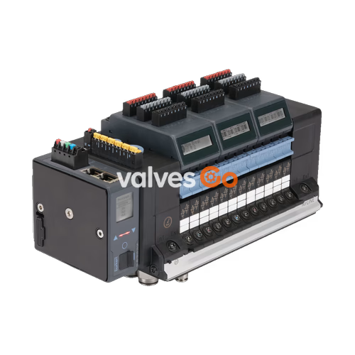
BURKERT 20016714 (Type 8652) is an AirLINE pneumatic valve island configured with 20 valve stations and an anodised aluminium AirLINE Quick adapter plate designed for direct mechanical mounting to control cabinet floors or walls. The assembly integrates an ME43 Industrial Ethernet communication module that natively supports PROFINET IO, EtherNet/IP, Modbus TCP, EtherCAT, and CC-Link IE Field Basic over dual RJ45 ports. Valve stations 1 through 14 contain 2x 3/2-way normally closed solenoid valves (Circuit Function C), stations 15 and 16 contain 5/2-way monostable solenoid valves (Circuit Function H), and stations 17 through 20 contain 2x 3/2-way normally closed valves equipped with SIA external shut-off contacts (Circuit Function C SIA) for safety-related hardware interlocking.
Pneumatic supply connection 1 (P) utilizes D10 mm push-in fittings in nickel-plated brass, while individual working ports 2 and 4 utilize D6 mm push-in brass fittings. Auxiliary pilot air is routed internally. The unit incorporates a dedicated pneumatic intermediate feed module positioned between station groups to balance air distribution across the 20-fold bank. An additional left-hand supply block provides secondary push-in connections for D6 and D10 mm tubing. The operating pressure spans from -1.00 bar vacuum up to 10.00 bar, with an auxiliary pilot pressure requirement of 3.00 to 10.00 bar and an ambient operating range of -10 °C to +55 °C.

The 20 valve positions of article 20016714 are populated with Type 6534 high-response 11 mm solenoid valve slices. Each station operates on 24 V DC with an initial inrush power of 0.7 W that reduces automatically to 0.175 W in continuous operation (100% duty cycle) to limit cabinet heat generation.
| Station Number | Valve Configuration | Circuit Function | Manual Override | Safety Shut-Off (SIA) |
|---|---|---|---|---|
| Slot 1 to 14 | 2x 3/2-way solenoid valve, normally closed | CF-C (WWC) | Latching / spring return | No |
| Slot 15 to 16 | 5/2-way monostable solenoid valve | CF-H (WWH) | Latching / spring return | No |
| Slot 17 to 20 | 2x 3/2-way solenoid valve, normally closed | CF-C SIA (WWC) | None (safety version) | Yes (dual external shut-off pins) |
Power Supply Isolation
Pneumatic valve coils (AUX 24 V) and communication/display electronics are powered through separate terminal blocks. This ensures diagnostic data and bus communication continue operating even if the valve power bus is disconnected by external safety relays.
The AirLINE Quick system allows the valve terminal to mount directly flush onto the bottom cut-out of a control cabinet, routing pneumatic lines directly out of the enclosure. This design eliminates individual bulkhead bulkhead fittings and internal tubing bundles.
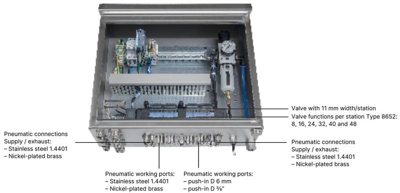
| Component | Material Specification |
|---|---|
| AirLINE Quick Adapter Plate | Anodised aluminium (1.4301 stainless steel optional on request) |
| Pneumatic Supply / Exhaust Ports | Brass, nickel-plated (push-in D10 mm, 3/8") |
| Pneumatic Working Ports | Brass, nickel-plated (push-in D6 mm, 1/4") |
| Valve Body Material | Polyamide (PA) |
| Seal Materials | NBR and PUR |
| Ingress Protection | IP20 stand-alone; IP65 when sealed into closed control cabinet |
| Control Cabinet Type Rating | Type 4X according to NEMA 250 (when using stainless steel plate variant) |
Article 20016714 uses the 20-fold baseplate configuration equipped with an intermediate supply block. Mounting utilizes M5 fasteners positioned along the baseplate perimeter.
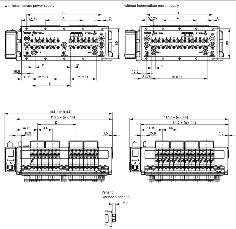
| Configuration Variant | A (mm) | B (mm) | C (Screws) | D (mm) | m | m' | n |
|---|---|---|---|---|---|---|---|
| 20-fold with intermediate supply (20016714) | 134 | 268 | 10 x M5 | 158.3 | 11 | 7 | 5 |
| 16-fold with intermediate supply | 112 | 224 | 10 x M5 | 114.3 | 7 | 7 | 4 |
| 24-fold with intermediate supply | 156 | 312 | 10 x M5 | 158.3 | 11 | 11 | 6 |
| 20-fold without intermediate supply | 121 | 242 | 10 x M5 | — | 19 | — | 5 |
Cabinet Clearance for Maintenance
Ensure adequate clearance between the control cabinet front door and the front edge of the valve slices. Adequate depth is necessary to allow hot-swap extraction of valve slices without bending adjacent wiring or dismantling air tubing.
Communication is managed via an integrated ME43 gateway supporting 100 Mbit/s Industrial Ethernet protocols with internal 2-port switching for line and ring topologies.
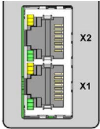
| Pin Number | Signal Name | Description |
|---|---|---|
| 1 | TX+ | Transmit data + |
| 2 | TX- | Transmit data - |
| 3 | RX+ | Receive data + |
| 4 | N.C. | Not connected |
| 5 | N.C. | Not connected |
| 6 | RX- | Receive data - |
| 7 | N.C. | Not connected |
| 8 | N.C. | Not connected |
| Terminal Block | Pin / Clip | Wire Colour | Signal Assignment | Conductor Cross-Section |
|---|---|---|---|---|
| 5-pin spring-loaded terminal | 1 | Red | 24 V DC (Logic and displays) | ≤ 1.5 mm² |
| 2 | White | CAN_H (büS interface) | ≤ 1.5 mm² | |
| 3 | Green | Shield | ≤ 1.5 mm² | |
| 4 | Blue | CAN_L (büS interface) | ≤ 1.5 mm² | |
| 5 | Black | 0 V DC (GND) | ≤ 1.5 mm² | |
| 2-pin spring-loaded terminal | 1 | Red | AUX 24 V DC (Pneumatic valve coils) | ≤ 1.5 mm² |
| 2 | Black | 0 V DC (GND) | ≤ 1.5 mm² |
Valve positions 17 through 20 feature Type 6534 SIA modules designed for safety shutdown. The coil circuit of each individual valve station is broken out to a dedicated external 2-pin pluggable terminal, permitting local hardware interlocks via dry contacts or safety relays.
| Electrical Parameter | Value |
|---|---|
| Terminal Type | Pluggable screw-type terminal, 2-pin, coded |
| Wire Cross-Section | 0.14 mm² to 1.5 mm² (AWG 28 to 16), rigid or flexible |
| Contact Switching Capacity | 0.5 A / 24 V DC |
| Default State upon Delivery | Fitted with electrical jumper bridges for immediate operation |
| Operational Requirement | Remove jumper bridge before connecting external dry contacts |
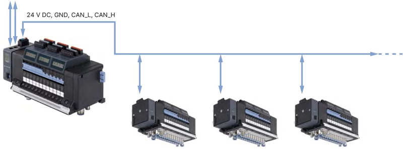
Article 20016714 can serve as an Industrial Ethernet master island, linking downstream büS slave valve blocks (such as secondary 8652 islands or Bürkert process valves) via its integrated service gateway.
Hazardous Area Restrictions
For installations in Zone 2 or Zone 22 hazardous areas, never connect or disconnect terminals while energized. Hot-swapping of pneumatic valves is prohibited in explosive atmospheres unless the zone is verified and certified to be free of flammable gas or dust.
Type 6534 pilot valves and mounting hardware are available as specific spare parts for servicing Type 8652 islands.
| Description | Circuit Function | Pressure Range | Flow Rate QNn | Article Number |
|---|---|---|---|---|
| Replacement Valve Type 6534 | 2x 3/2-way CF-C, 24 V DC | Vac. to 10 bar | 270 l/min | 301374 |
| Replacement Valve Type 6534 | 5/2-way CF-H, 24 V DC | Vac. to 10 bar | 290 l/min | 301376 |
| Replacement Valve Type 6534 SIA | 2x 3/2-way CF-C SIA, 24 V DC | Vac. to 10 bar | 270 l/min | 338802 |
| Replacement Valve Type 6534 SIA | 5/2-way CF-H SIA, 24 V DC | Vac. to 10 bar | 290 l/min | 338805 |
| Dummy Valve Slice | Blanking plate for unused slot | — | — | 335779 |
| 5-Pin Spring Terminal Plug | Power supply logic and displays | — | — | 920180 |
| 2-Pin Spring Terminal Plug | Power supply valve coils (AUX) | — | — | 920442 |
| ME43 Gateway Module | Industrial Ethernet communication | — | — | 301799 |
| AirLINE Quick 20-Fold Height Adapter | For 20-fold base with intermediate feed | — | — | 754963 |
| AirLINE Quick 20-Fold Retaining Plate | Exterior cabinet fixing plate | — | — | 60005569 |
Explore similar products in our catalog


