

PN16

BURKERT 20017767 (Type 8652) AirLINE is a 24-slot modular pneumatic valve island with Industrial Ethernet, 48 digital inputs, D10 supply, D6 working ports, and pneumatic HotSwap.
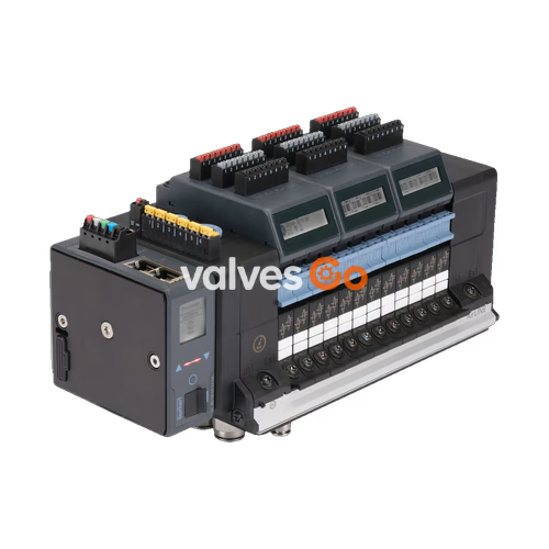
BURKERT 20017767 (Type 8652) AirLINE is a modular pneumatic valve island configured with 24 valve slots, designed for piloting pneumatic loads in automated process control systems. The assembly integrates an aluminium AirLINE Quick base adapter, brass push-in connections for compressed air distribution, internal auxiliary pilot air supply, and an Industrial EtherNet communication module. It provides full industrial network connectivity supporting PROFINET IO, EtherNet/IP, Modbus TCP, EtherCAT, and CC-Link IE Field Basic over an RJ45 interface, alongside 48 onboard digital inputs distributed across six electrical input modules.
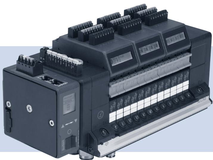
The 20017767 configuration incorporates 24 valve positions, each occupied by a dual 3/2-way normally closed pneumatic valve slice (2x 3/2-way CF-C), delivering a total of 48 independently controlled valve functions. The pneumatic interface includes integrated check valves in exhaust ducts 3 (R) and 5 (S) to prevent backpressure interaction, as well as pneumatic HotSwap capability on supply port 1 (P).
| Valve Position | Configured Valve Type | Switching Logic | Circuit Function |
|---|---|---|---|
| Slot 1 to Slot 24 | 2x 3/2-way | Normally Closed (NC) | CF-C |
Additional mechanical and supply characteristics:
| Parameter | Value |
|---|---|
| Model Identifier | 20017767 |
| Device Type | 8652 AirLINE |
| Product Variant | Standard fieldbus module |
| Number of Valve Slots | 24 PCE (up to 48 valve functions) |
| Pilot Valve Element | Type 6164 (piloting Type 6534 pneumatic valves) |
| Operating Pressure Range | -1.00 bar to 10.00 bar |
| Pilot Pressure Range | 3.00 bar to 10.00 bar |
| Medium Temperature | -10 °C to +55 °C |
| Ambient Temperature | -10 °C to +55 °C |
| Supply Port Size / Material | D10 push-in connector / Brass |
| Working Port Size / Material | D6 push-in connector / Brass |
| Adapter Material | AirLINE Quick Aluminium |
| Rated Operating Voltage | 24 V DC (±10%) |
| Nominal Current Consumption | Up to 3 A (structure-dependent) |
| Communication Protocols | Industrial EtherNet (PROFINET IO, EtherNet/IP, Modbus TCP, EtherCAT, CC-Link IE Field Basic) |
| Communication Hardware Interface | RJ45 |
| Digital Input Capacity | 48 Digital Inputs (6 electronic modules with DI) |
| Integrated Check Valves | Port 3 (R) and Port 5 (S) |
| Pneumatic HotSwap | Port 1 (P) |
| Ingress Protection Rating | IP20 (with suitable mating connectors) |
Type 8652 AirLINE valve islands comply with ATEX Directive 2014/34/EU, IECEx scheme rules, and national explosion protection standards (GB/T 3836.2021 by SITIIAS, CCC certified). Type examination certificates BVS 20 ATEX E 031 U and IECEx BVS 20.0024 U are issued by DEKRA Testing and Certification GmbH (BVS Bochum), with production quality surveillance audited by PTB (CE0102).
When installed in a control cabinet with an ambient internal temperature up to +55 °C, the assembly remains within temperature class T4 limits. For AirLINE Quick variants, the maximum exterior operating temperature does not exceed 80 °C.
Valve islands designated for hazardous locations carry two nameplates: a general nameplate and an explosion protection certification plate.
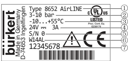
| Position | Description | Value / Example |
|---|---|---|
| 1 | Device Type | Type 8652 AirLINE |
| 2 | Pressure Range | 3–10 bar (pilot) / -1–10 bar (nominal) |
| 3 | Ambient Temperature Range | -10 °C to +55 °C |
| 4 | Rated Voltage / Current Consumption | 24 V DC / 3 A |
| 5 | Serial Number | S/N (factory encoded) |
| 6 | Manufacturing Code | Encoded date code |
| 7 | Order Article Number | 20017767 |
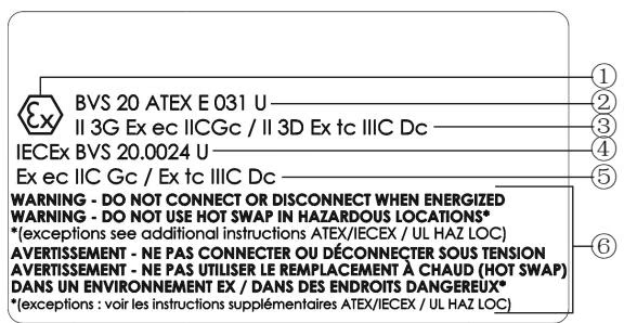
| Position | Designation (Code PX68) | Specification Data |
|---|---|---|
| 1 | Explosion Protection Symbol | Ex mark |
| 2 | ATEX Certificate Number | BVS 20 ATEX E 031 U |
| 3 | ATEX Gas / Dust Marking | II 3G Ex ec IIC Gc / II 3D Ex tc IIIC Dc |
| 4 | IECEx Certificate Number | IECEx BVS 20.0024 U |
| 5 | IECEx Gas / Dust Marking | Ex ec IIC Gc / Ex tc IIIC Dc |
| 6 | Safety Advisory | Electrical connections and HotSwap instructions |
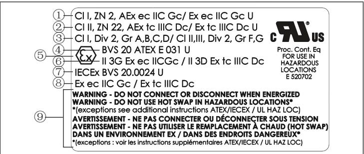
| Position | Designation (Code PU17) | Specification Data |
|---|---|---|
| 1 | US/CA Zone Marking (Gas) | Cl I, ZN 2, AEx ec IIC Gc / Ex ec IIC Gc U |
| 2 | US/CA Zone Marking (Dust) | Cl II, ZN 22, AEx tc IIIC Dc / Ex tc IIIC Dc U |
| 3 | US/CA Division Marking (Gas / Dust) | Cl I, Div 2, Gr A, B, C, D / Cl II, III, Div 2, Gr F, G |
| 4 | ATEX Certificate Number | BVS 20 ATEX E 031 U |
| 5 | Explosion Protection Symbol | Ex mark |
| 6 | ATEX Gas / Dust Marking | II 3G Ex ec IIC Gc / II 3D Ex tc IIIC Dc |
| 7 | IECEx Certificate Number | IECEx BVS 20.0024 U |
| 8 | IECEx Gas / Dust Marking | Ex ec IIC Gc / Ex tc IIIC Dc |
| 9 | Safety Advisory | Electrical connections and HotSwap instructions |
Enclosure Protection Requirements
For Type of Protection "ec" (gas atmosphere, Category 3G / Gc), the device must be installed inside a control cabinet or enclosure providing at least IP54 ingress protection in accordance with EN/IEC 60079-0 and EN/IEC 60079-7. For Type of Protection "tc" (dust atmosphere, Category 3D / Dc), the enclosure must provide at least IP6X ingress protection (minimum IP64) conforming to EN/IEC 60079-0 and EN/IEC 60079-31. The enclosure must be certified for hazardous area service and adequately dimensioned to dissipate thermal load so the internal temperature does not exceed +55 °C.
Operating Restrictions in Potentially Explosive Atmospheres
An auxiliary adhesive warning label is supplied with the unit reading: WARNING DO NOT CONNECT OR DISCONNECT WHEN ENERGIZED. If the primary explosion protection nameplate is obscured after cabinet mounting, apply this label visibly on the valve island body.
Explore similar products in our catalog


