

PN16

Burkert 20032009 (Type 0121) is a direct-acting 3/2-way pivoted armature solenoid valve with media separation, PVC body, FKM seals, DN 8 orifice, G 3/8 ports, and 24 V AC/DC operation for corrosive media.
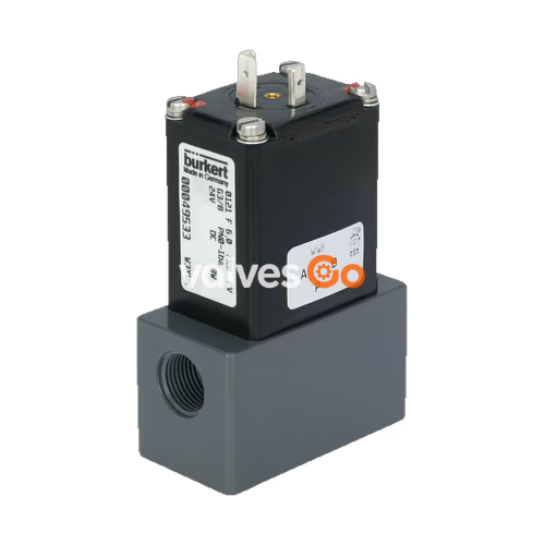
BURKERT 20032009 (Type 0121) is a direct-acting, media-separated 3/2-way pivoted armature solenoid valve engineered for controlling aggressive acids, alkaline lyes, salt solutions, and waste gases. Built with a solid PVC body, chemical-resistant FKM seals, and an internal G 3/8 port connection, this valve delivers complete hermetic isolation between fluid channels and the electromagnetic actuator.
Operating in Circuit Function C (normally closed), the valve accommodates operating pressures from 0 to 0.3 bar across liquid media and gases. It provides an 8.0 mm (5/16") orifice with a water flow capacity of 1.0 m³/h (Kv) and a normalized gas flow rate of 1,000 l/min (QNn). The epoxy-encapsulated coil runs on 24 V AC/DC (50/60 Hz) and features an integrated manual override for commissioning, functional testing, and emergency cycling.
Type 0121 isolates fluid contact via an elastomer diaphragm interposed directly between the valve body and the pivoted armature mechanism. Because process media cannot enter the armature cavity or contact metallic magnetic components, internal chemical buildup and corrosion are eliminated.
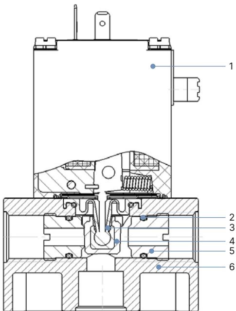
The pivoted armature design delivers fast direct action without requiring differential operating pressure. The coil system is molded with chemically resistant epoxy and firmly screwed into a rigid block construction to maintain alignment under mechanical vibration.
| Item | Component | Material |
|---|---|---|
| 1 | Coil | Epoxy (insulation class H) |
| 2 | O-ring | FKM |
| 3 | Toggle pin | PTFE |
| 4 | Isolating diaphragm seal | FKM (70 Shore A) |
| 5 | Valve seat | PVC (polyvinyl chloride) |
| 6 | Valve body | PVC (polyvinyl chloride, DIN 8062/8061) |
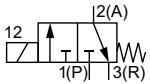
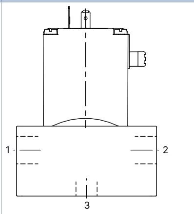
Model 20032009 is configured in Circuit Function C (normally closed 3/2-way valve). Fluid flow enters below the valve seat, providing steady shutoff against positive backpressure.
| Circuit Function | Connection 1 | Connection 2 | Connection 3 | Flow Path De-energized | Flow Path Energized |
|---|---|---|---|---|---|
| CF C (Normally Closed) | P (Pressure inlet, NC) | R (Exhaust / return, NO) | A (Working outlet, OUT) | Port 1 (P) closed; Port 3 (A) vents to Port 2 (R) | Port 1 (P) opens to Port 3 (A); Port 2 (R) closed |
| CF D (Normally Open) | R | P | B | Port 2 (P) flows to Port 3 (B); Port 1 (R) closed | Port 2 (P) closed; Port 3 (B) vents to Port 1 (R) |
| CF E (Mixing Valve) | P1 | P2 | A | Port 2 (P2) flows to Port 3 (A); Port 1 (P1) closed | Port 1 (P1) flows to Port 3 (A); Port 2 (P2) closed |
| CF F (Distribution Valve) | A | B | P | Port 3 (P) flows to Port 2 (B); Port 1 (A) closed | Port 3 (P) flows to Port 1 (A); Port 2 (B) closed |
| Parameter | Value |
|---|---|
| Burkert Article Number | 20032009 |
| Valve Type Family | Type 0121 |
| Valve Configuration | Complete direct-acting 3/2-way pivoted armature valve |
| Circuit Function | C (normally closed) |
| Orifice Size | DN 8.0 mm (5/16") |
| Port Thread Size | G 3/8 internal thread (DIN ISO 228/1) |
| Flow Capacity Kv (Water) | 1.0 m³/h |
| Flow Capacity QNn (Gas) | 1,000 l/min |
| Pressure Range (Liquids & Gases) | 0...0.3 bar gauge |
| Body & Seat Material | PVC (polyvinyl chloride) |
| Seal Material (Internal & External) | FKM (fluororubber, 70 Shore A) |
| Nominal Operating Voltage | 24 V AC/DC (50/60 Hz) |
| Voltage Tolerance | ±10% |
| AC Power Consumption | Inrush: 30 VA; Hold: 15 VA (8 W) |
| DC Power Consumption | Cold: 11 W; Warm: 8 W |
| Permissible Duty Cycle | 10% ED (10 min base cycle) with standard 8 W coil on PVC body |
| Maximum Switching Frequency | 100 cycles/min (AC) |
| AC Response Times | Opening: 20 ms; Closing: 11 ms |
| DC Response Times | Opening: 11 ms; Closing: 8 ms |
| Fluid Temperature Range | -10 °C...+50 °C |
| Maximum Ambient Temperature | +50 °C |
| Maximum Kinematic Viscosity | 37 mm²/s |
| Total Net Weight | 0.38 kg |
Thermal Duty Cycle Limitation with PVC Housing
Due to the lower thermal conductivity of PVC compared to metallic materials, standard 8 W coil assemblies installed on PVC housings are restricted to a 10% operating duty cycle (within a 10-minute cycle window) under continuous energization. Where 100% continuous duty (continuous energization) is required on PVC bodies, valves must be specified with high-performance electronic power-reduction coils (Option CZ05: 60 W inrush, 3 W nominal holding) or a 5 W reduced-power coil.
Model 20032009 standard variant features a compact body footprint with an overall length of 65 mm.
| Body Material | Thread D | Total Height B [mm] | Width E [mm] | Overall Length F [mm] |
|---|---|---|---|---|
| PVC (Item 20032009) | G 3/8 | 91 | 35 | 65 |
| Stainless Steel 1.4401 | G 1/4 | 89 | 32 | 76 |
| PTFE | G 3/8 | 91 | 35 | 76 |
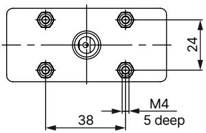
Mechanical mounting is accomplished via M4 × 5 mm female threaded holes located on the bottom face of the valve body, spaced according to a 38 mm × 24 mm pattern.
The standard coil terminates in three male spade contacts conforming to DIN EN 175301-803 Form A. The matching cable plug is not included with the bare valve body and must be ordered separately.
| Accessory Description | Type / Model | Voltage Range | Article Number |
|---|---|---|---|
| Cable Plug Form A without circuitry | Type 2518 | 0...250 V AC/DC | 314802 |
| Cable Plug Form A with status LED | Type 2518 | 12...24 V AC/DC | 314812 |
| Cable Plug Form A with LED and varistor | Type 2518 | 12...24 V AC/DC | 314820 |
| Cable Plug Form A with rectifier, LED, varistor | Type 2518 | 12...24 V AC/DC | 314816 |
| Standard Cable Plug Form A without circuitry | Type 2509 | 0...250 V AC/DC | 137943 |
| Solid-State Timer (Form A DIN EN 175301-803) | Type 1087 | 12...24 V AC/DC | Specification dependent |
| Anti-Tamper Circlip for Manual Override | Locking clip | — | 013372 |
Manual Override Locking Clip
The manual override allows manual opening or testing without electrical power. To safeguard against accidental mechanical activation in safety-critical dosing or chemical lines, install the optional circlip (Part No. 013372).
Piping and Position Recommendations
Explore similar products in our catalog


