

PN16

BURKERT 20032526 (Type 8652 AirLINE) is a 20-slot pneumatic valve island with stainless steel AirLINE Quick interface, Industrial Ethernet RJ45 fieldbus, and operating pressure from -1 to 10 bar.
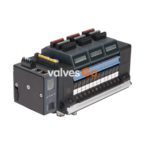
BURKERT 20032526 (Type 8652 AirLINE) is a preconfigured 20-slot modular valve terminal engineered specifically for process automation installations. This specific article combines an Industrial Ethernet communication interface supporting PROFINET IO, EtherNet/IP, Modbus TCP, EtherCAT, and CC-Link IE Field Basic via two RJ45 ports with a stainless steel AirLINE Quick base plate. The assembly accommodates 20 valve stations in an 11 mm slice grid, comprising 14 bistable 5/2-way valves, 3 double 3/2-way normally closed valves, 1 monostable 5/2-way valve, 2 blind covers, and 1 intermediate supply module for optimized air distribution.
Operating across a pneumatic pressure span of -1.00 bar to 10.00 bar with internal pilot air delivery between 3 bar and 10 bar, BURKERT 20032526 integrates stainless steel push-in fittings: D 3/8" on the air supply and exhaust ports and D 1/4" on the actuator working lines. An LC display on the terminal visualizes diagnostic text and standardized icons directly at the unit, while diagnostic telemetry is routed over the industrial network to the supervisory PLC. The electrical subsystem is rated for 24 V DC (±10%) and incorporates an electronic input module supplying 8 digital inputs for field sensor feedback.

Article 20032526 is factory-assembled with a dedicated valve slice layout across its 20 stations. The pilot valves utilize low-wear miniature solenoid technology operating at 24 V DC with an initial nominal coil power of 0.7 W, dropping automatically to 0.175 W (10 mA) after actuation to minimize heat generation within control cabinets.
| Valve Position | Circuit Function | Description | Manual Override | Nominal Flow Rate (QNn) |
|---|---|---|---|---|
| Position 1 to 14 | CF-Z | 5/2-way solenoid valve, impulse/bistable with 2 coils | Latching / spring return | 290 l/min |
| Position 15 to 17 | CF-C | 2x 3/2-way solenoid valve, normally closed | Latching / spring return | 270 l/min |
| Position 18 | CF-H | 5/2-way solenoid valve, monostable/spring return | Latching / spring return | 290 l/min |
| Position 19 | Blind plate | Dummy plate for pneumatic sealing and future expansion | None | — |
| Position 20 | Blind plate | Dummy plate for pneumatic sealing and future expansion | None | — |
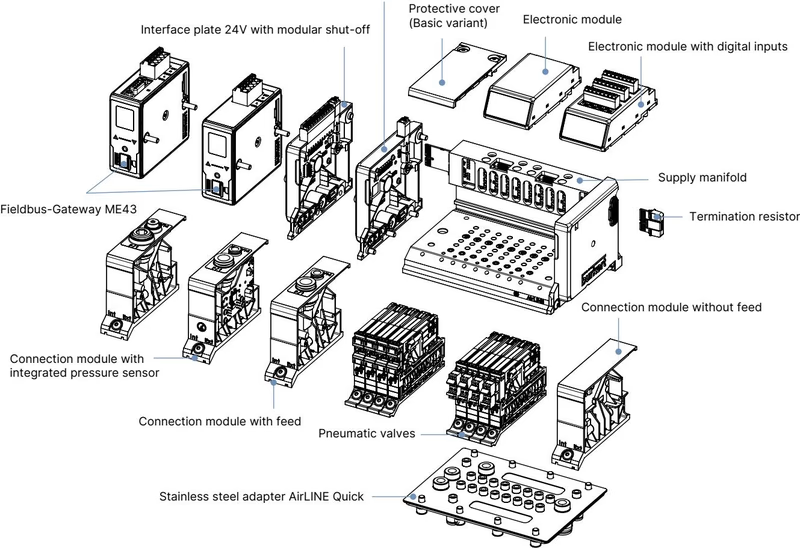
Each pneumatic slice features an individual station width of 11 mm. The integrated intermediate pneumatic feed module (1 PCE) is installed between the valve slices to deliver additional supply volume and balance exhaust backpressures across the 20-bank manifold.
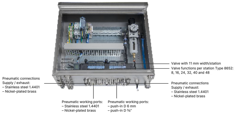
Article 20032526 features the AirLINE Quick adapter system constructed from stainless steel 1.4301 (ALQ VA) with stainless steel 1.4401 push-in pneumatic connections. This mechanical interface mounts directly through a cutout in the control cabinet bottom or wall, eliminating individual panel-mount bulkhead fittings and internal cabinet pneumatic tubing.
| Parameter Group | Technical Parameter | Value / Specification |
|---|---|---|
| Pneumatic Data | Working medium | Dry lubricated or oil-free compressed air, neutral gases (5 µm filtration recommended) |
| Air quality class | ISO 8573-1:2010, Class 7.4.4 | |
| Working pressure range | Vacuum to 10 bar (-1.00 bar to 10.00 bar) | |
| Auxiliary pilot pressure | 3 bar to 10 bar (internal auxiliary pilot air) | |
| Standard nominal flow (QNn) | 310 l/min (measured at +20 °C, 6 bar inlet pressure, 1 bar pressure difference) | |
| Operating mode | Continuous operation (100% duty cycle) | |
| Valve switching times | Opening: 15–20 ms, Closing: 15–25 ms (measured according to ISO 12238) | |
| Electrical Data | Operating voltage | 24 V DC (±10%) |
| Residual ripple | 1 Vss | |
| Nominal power per valve | 0.7 W per coil (0.175 W after holding current reduction) | |
| Nominal current per valve | 29 mA (10 mA after current reduction) | |
| Protection class | Class III according to DIN EN 61140, VDE 0140 | |
| Mechanical & Materials | Body housing material | PA (Polyamide) |
| Seal materials | NBR and PUR | |
| Adapter plate material | Stainless steel 1.4301 | |
| Pneumatic port fittings | Stainless steel 1.4401 | |
| Station width per valve | 11 mm | |
| Thermal & Ambient | Ambient temperature range | -10 °C to +55 °C |
| Medium temperature range | -10 °C to +55 °C | |
| Storage temperature range | -20 °C to +60 °C | |
| Degree of protection | IP20 (bare unit), IP65 (installed on closed cabinet with AirLINE Quick) |
BURKERT 20032526 incorporates an ME43 fieldbus gateway module configured for multi-protocol Industrial Ethernet. Network integration is implemented through two M12-equivalent RJ45 ports (X1 and X2), enabling line and ring topologies without requiring external industrial switches.
| Pin | Signal | Assignment Description |
|---|---|---|
| 1 | TX+ | Transmit Data + |
| 2 | TX- | Transmit Data - |
| 3 | RX+ | Receive Data + |
| 4 | N.C. | Not connected |
| 5 | N.C. | Not connected |
| 6 | RX- | Receive Data - |
| 7 | N.C. | Not connected |
| 8 | N.C. | Not connected |
Separate Power Supplies
The valve terminal utilizes physically separated power connections for electronics and valve actuators. Logic, communications, and LC displays are energized via a 5-pin spring-loaded terminal. Solenoid valve coils are powered through an independent 2-pin spring-loaded auxiliary terminal (AUX 24 V). This allows emergency disconnection of valve actuation power without dropping network communication or process diagnostics.
| Terminal Block | Terminal / Pin | Wire Colour | Assignment |
|---|---|---|---|
| 5-pin spring-loaded terminal (Logic & Display) | Pin 1 | Red | +24 V DC |
| Pin 2 | White | CAN_H (büS connection) | |
| Pin 3 | Green | Shielding | |
| Pin 4 | Blue | CAN_L (büS connection) | |
| Pin 5 | Black | GND (0 V DC) | |
| 2-pin spring-loaded terminal (Valve Actuation Power) | Terminal 1 | Red | AUX 24 V DC |
| Terminal 2 | Black | GND (0 V DC) |
Both terminal connections accept rigid or flexible conductors up to 1.5 mm² cross-section.
In article 20032526, electronic module 5 is equipped with an 8-channel digital input board (8DI), providing feedback processing from discrete plant sensors and limit switches.
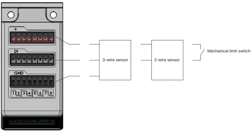
| Diagnostic Condition | 3-Wire Sensors | 2-Wire Sensors | Mechanical Limit Switches |
|---|---|---|---|
| Sensor actuated | Yes | Yes | Yes |
| Sensor not actuated | Yes | Yes | Yes |
| Short-circuit detection | Yes | — | — |
| Wire-break detection | — | Yes | — |
BURKERT 20032526 can function as a primary master valve terminal on Industrial Ethernet while coordinating downstream büS/CANopen valve islands or Bürkert EDIP devices.
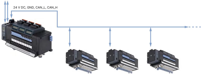
Parameters, cycle configurations, and live diagnostic monitoring can be managed via Bürkert Communicator software (Type 8920) through a USB büS interface set.
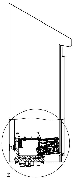
Mounting inside an electrical enclosure requires maintaining specific physical clearances around the valve slices and AirLINE Quick plate.
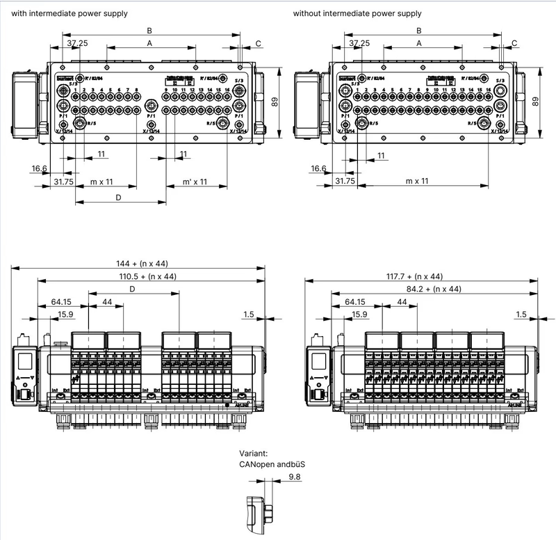
| Dimension Code | Description | Value (mm) |
|---|---|---|
| A | Mounting hole spacing to intermediate module | 134 mm |
| B | Total mounting hole length span | 268 mm |
| C | Fastening screw holes | 10 x M5 |
| D | Center-to-center offset dimension | 158.3 mm |
| m | Valve station count group 1 | 11 slots |
| m' | Valve station count group 2 | 7 slots |
| n | Mounting section count | 5 |
Maintenance Clearance
When positioning the valve island within the cabinet, maintain adequate clearance to the front door and side panels to facilitate module servicing and display inspection. Refer to the Type 8652 operating instructions for exact spatial guidelines.
BURKERT 20032526 complies with the following industrial standards and safety certifications:
Hazardous Location Operations
For installations in classified hazardous environments (ATEX/IECEx Zone 2/22, cURus HazLoc Class I Div 2 Groups A–D, Class II/III Div 2 Groups F–G):
| Circuit Function | Operating Principle | QNn (Air) | Pressure Range | Opening Time | Closing Time | Voltage | Order Article No. (incl. screws) |
|---|---|---|---|---|---|---|---|
| CF-Z | 5/2-way bistable impulse with 2 coils | 290 l/min | Vac. to 10 bar | 20 ms | 25 ms | 24 V DC | 301377 (Spare set: 296034) |
| CF-C | 2x 3/2-way normally closed | 270 l/min | Vac. to 10 bar | 15 ms | 15 ms | 24 V DC | 301374 (Spare set: 296031) |
| CF-H | 5/2-way monostable | 290 l/min | Vac. to 10 bar | 20 ms | 25 ms | 24 V DC | 301376 (Spare set: 296033) |
| Blind Plate | Dummy valve cover | — | — | — | — | — | 335779 (Spare set: 327614) |
| Item Description | Quantity | Order Article No. |
|---|---|---|
| Spring-loaded terminal 5-pin (Logic and LC display power supply) | 1 PCE | 920180 |
| Spring-loaded terminal 2-pin (Valve actuation power AUX 24 V) | 1 PCE | 920442 |
| ME43 Fieldbus Gateway Module (Industrial Ethernet: PROFINET, EtherNet/IP, Modbus TCP, EtherCAT) | 1 PCE | 301799 |
| AirLINE Quick Height Adapter for 20-slot base with intermediate feed | 1 PCE | 754963 |
| AirLINE Quick Retaining Plate for 20-slot base with intermediate feed | 1 PCE | 60005569 |
| AirLINE Quick Blind Plate for 20-slot base with intermediate feed | 1 PCE | 754968 |
| Fastening screw set M5 x 10 A2 DIN 6912 (for securing island to cabinet floor) | 10 PCE | 308661 |
| USB büS Interface Set 1 (Type 8923) for Bürkert Communicator software | 1 Set | 772426 |
| Bürkert Communicator Software | Software | Type 8920 |
Explore similar products in our catalog


