

PN16

BURKERT 20032688 Type 8652 AirLINE is an 8-slot pneumatic valve island with PROFIBUS DPV1, AirLINE Quick aluminium adapter plate, 16 CF-C valve functions, integrated check valves, and pneumatic HotSwap.
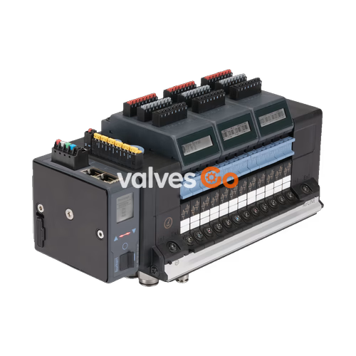
BURKERT 20032688 (Type 8652 AirLINE) is an 8-slot modular pneumatic valve island configured for process automation in control cabinets. Fitted with an AirLINE Quick anodised aluminium base plate, this unit provides 8 valve slots equipped with dual 3/2-way normally closed solenoid valves (Circuit Function C), yielding 16 independently controlled pneumatic valve functions. Process connections feature push-in D10 mm brass supply ports (port 1) and push-in D6 mm brass working ports (ports 2 and 4). Integrated check valves in exhaust ducts 3 (R) and 5 (S) prevent unintentional actuator movement caused by backpressure spikes, while integrated pneumatic HotSwap functionality at port 1 (P) enables individual valve replacement during ongoing plant operation without pressure interruption.
Communication is handled by an integrated PROFIBUS DPV1 interface module via a 9-pin Sub-D connector. Diagnostic parameters and valve switching states are visualised directly on the built-in LC display in clear text and standardized symbols, and transmitted cyclically to the higher-level PLC. The valve island is rated for continuous operation (100% duty cycle) across an operating pressure range of vacuum to 10 bar (-1.00 bar to 10.00 bar), with an auxiliary pilot air supply requirement of 3 bar to 10 bar.
| Parameter | Specification |
|---|---|
| Type | 8652 AirLINE |
| Article number (Ident number) | 20032688 |
| Number of valve slots | 8 slots (11 mm station width each) |
| Installed valve functions | 16 (8 slots × dual 3/2-way CF-C) |
| Body material | Polyamide (PA) |
| Seal materials | NBR and PUR |
| AirLINE Quick adapter plate | Anodised aluminium |
| Supply connection (port 1) | Push-in fitting D10 mm, nickel-plated brass |
| Working ports (ports 2 and 4) | Push-in fitting D6 mm, nickel-plated brass |
| Auxiliary pilot air | Internal supply |
| Intermediate feed modules | 0 (none required for 8-slot configuration) |
| Operating pressure range | Vacuum to 10 bar (-1.00 bar to 10.00 bar) |
| Auxiliary pilot pressure range | 3 bar to 10 bar |
| Nominal flow rate QNn (air) | 310 l/min (measured at +20 °C, 6 bar inlet, 1 bar Δp; approx. 3% flow reduction with HotSwap) |
| Operating medium | Compressed dry air (lubricated or oil-free), neutral gases |
| Compressed air quality | ISO 8573-1:2010, Class 7.4.4 (5 µm filtration recommended) |
| Operating voltage | 24 V DC (±10%, residual ripple 1 Vss) |
| Power per valve coil | 0.7 W nominal (0.175 W after electronic power reduction) |
| Current per valve coil | 29 mA nominal (10 mA after electronic power reduction) |
| Digital inputs | 0 (without DI electronic module) |
| Degree of protection | IP20 (bare) / IP65 (installed with AirLINE Quick in closed control cabinet) |
| Ambient operating temperature | -10 °C to +55 °C |
| Fluid / medium temperature | -10 °C to +55 °C |
| Storage temperature | -20 °C to +60 °C |
| Duty cycle | Continuous operation (100% ED) |
| Protection class | III according to DIN EN 61140, VDE 0140 |
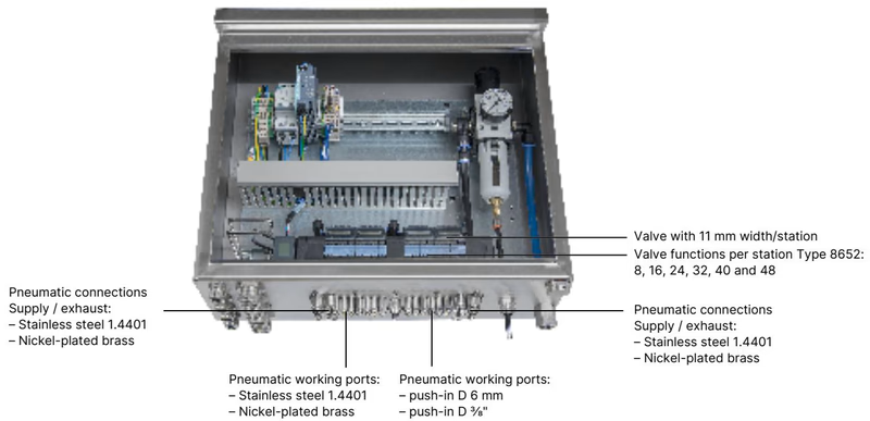
AirLINE Quick allows direct mechanical and pneumatic installation onto the control cabinet floor or wall, eliminating bulkhead feedthrough fittings. All pneumatic connections for supply air, exhaust air, and working lines pass through the cabinet base plate.
Article 20032688 is configured with 8 valve slots, each populated with a Type 6534 dual 3/2-way servo-controlled solenoid valve in Circuit Function C (normally closed). Each valve module operates with latching manual override (spring return) and 11 mm width per station.
| Position | Circuit Function | Description | QNn (Air) | Switching Time Opening | Switching Time Closing |
|---|---|---|---|---|---|
| Slot 1 to 8 | 2 × 3/2-way CF-C | Dual 3/2-way solenoid valve, servo-controlled, normally closed, with manual override | 270 l/min | 15 ms | 15 ms |
Integrated exhaust check valves in ports 3 and 5 prevent back-venting into unpressurised actuator chambers when adjacent valves discharge. The integrated pneumatic HotSwap function at port 1 incorporates a shut-off mechanism that permits individual valve removal under working pressure while the remaining 7 valve stations continue running.
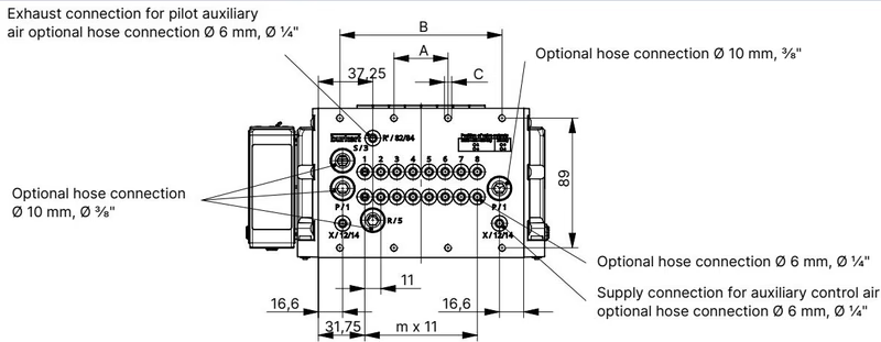
Dimensions for 4-, 8-, and 12-slot configurations according to Type 8652 technical documentation (all dimensions in mm):
| Configuration | A (mm) | B (mm) | C | m | n |
|---|---|---|---|---|---|
| 4-slot | 66 | — | 4 × M5 | 3 | 1 |
| 8-slot (20032688) | 35 | 111 | 8 × M5 | 7 | 2 |
| 12-slot | 77 | 154 | 10 × M5 | 11 | 3 |
The assembly can alternatively be mounted on standard DIN rails (EN 50022, 35 × 7.5 mm or 35 × 15 mm). When installing inside a control cabinet, clearance to the front edge and rear wall must be maintained.
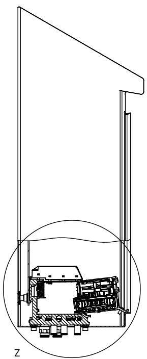
Control Cabinet Clearance for Hot Swap
To enable unimpeded replacement of valve modules under HotSwap operation, observe the minimum clearance to the front edge of the control cabinet specified in the Type 8652 operating manual. Ensure adequate spacing between the cabinet rear wall and the mounting plate for cable routing and air line radius.
The valve island utilizes separate power supplies for the electronic communication/display circuits and the pneumatic valve coils to permit emergency shutdown of valve outputs without disrupting fieldbus communication.
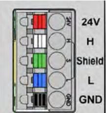
| Pin | Colour | Assignment |
|---|---|---|
| 1 | Red | 24 V DC |
| 2 | White | CAN_H (büS connection) |
| 3 | Green | Shielding |
| 4 | Blue | CAN_L (büS connection) |
| 5 | Black | GND (0 V DC) |
Permissible conductor cross-section is ≤ 1.5 mm².
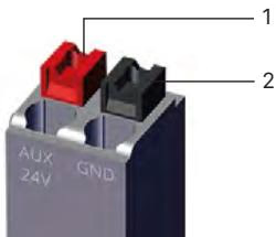
| Clip | Colour | Assignment |
|---|---|---|
| 1 | Red | AUX 24 V DC |
| 2 | Black | GND (0 V DC) |
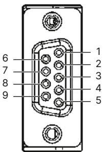
| Pin | Signal | Description |
|---|---|---|
| 1 | Shielding | Cable shield / ground |
| 2 | M24 | 24 V ground return (optional) |
| 3 | RxD/TxD-P | Receive / Transmit data positive (B-line) |
| 4 | CNTR-P | Control signal P (repeater direction control, optional) |
| 5 | DGND | Data ground (0 V) |
| 6 | +5 V | +5 V DC termination power supply |
| 7 | +24 V | 24 V DC power supply (optional) |
| 8 | RxD/TxD-N | Receive / Transmit data negative (A-line) |
| 9 | CNTR-N | Control signal N (optional) |
Diagnostic Display and Monitoring
The built-in LC display shows diagnostic notifications in plain text and symbols. Operating status, error codes, and channel states can be evaluated at the cabinet floor without external configuration tools, while cyclical diagnostics are reported via PROFIBUS DPV1 to the process controller.
Article 20032688 complies with explosion protection standards for equipment category 3 in Zone 2 (gas) and Zone 22 (dust):
| Standard / Authority | Marking | Certificate Number |
|---|---|---|
| ATEX | II 3G Ex ec IIC Gc II 3D Ex tc IIIC Dc | BVS 20 ATEX E 031 U |
| IECEx | Ex ec IIC Gc Ex tc IIIC Dc | IECEx BVS 20.0024 U |
| CCC | Certified for hazardous areas in China | GB/T 3836 series |
| cURus HazLoc | Class I, Zone 2, AEx ec IIC Gc / Ex ec IIC Gc U Class II, Zone 22, AEx tc IIIC Dc / Ex tc IIIC Dc U Class I, Division 2, Groups A, B, C, D Class II, III, Division 2, Groups F, G | E-file certification |
Hazardous Area Operating Restrictions
Individual valve slices on the 8652 island are replaceable as spare parts. For article 20032688, replacement valves correspond to Type 6534:
| Circuit Function | Orifice | QNn (Air) | Pressure Range | Voltage | Replacement Valve Part No. | Spare Part Set Part No. |
|---|---|---|---|---|---|---|
| 2 × 3/2-way CF-C (installed) | 4 mm | 270 l/min | Vac. to 10 bar | 24 V DC | 301374 | 296031 |
| 2 × 3/2-way CF-D | 4 mm | 310 l/min | Vac. to 10 bar | 24 V DC | 301375 | 296032 |
| 5/2-way CF-H | 4 mm | 290 l/min | Vac. to 10 bar | 24 V DC | 301376 | 296033 |
| 5/2-way impulse CF-Z | 4 mm | 290 l/min | Vac. to 10 bar | 24 V DC | 301377 | 296034 |
| 5/3-way CF-L (closed mid) | 4 mm | 275 l/min | Vac. to 10 bar | 24 V DC | 301380 | 296036 |
| 5/3-way CF-M (pressurised mid) | 4 mm | 300 l/min | Vac. to 10 bar | 24 V DC | 301379 | 296035 |
| 5/3-way CF-N (exhausted mid) | 4 mm | 300 l/min | Vac. to 10 bar | 24 V DC | 301381 | 296039 |
| Dummy valve plate | — | — | — | — | 335779 | 327614 |
| Description | Quantity | Article Number |
|---|---|---|
| Screw set M5 × 10 A2 DIN 6912 (base fastening) | 10 pcs | 308661 |
| Height adapter for 8-fold base (without intermediate feed) | 1 pc | 754960 |
| Retaining plate for 8-fold base (cabinet exterior) | 1 pc | 60005566 |
| Blind plate for 8-fold base | 1 pc | 754965 |
| 5-pin spring-loaded terminal (electronics/display) | 1 pc | 920180 |
| 2-pin spring-loaded terminal (valve supply AUX 24 V) | 1 pc | 920442 |
Explore similar products in our catalog


