

PN16

Burkert 20033682 (Type 6027) is an ATEX/IECEx certified direct-acting 2/2-way NC solenoid plunger valve in stainless steel, featuring G 1/4 ports, 4 mm orifice, PTFE seal, Kick and Drop coil, and 3 m cable.
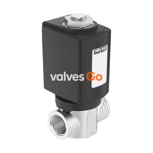
BURKERT 20033682 (Type 6027) is a direct-acting 2/2-way normally closed (NC) solenoid plunger valve engineered for demanding neutral, slightly aggressive, and gaseous fluids up to 25 bar. The unit features an investment cast stainless steel 1.4404 (316L) body with G 1/4 internal thread ports, a 4.0 mm nominal orifice, and an overall face-to-face length of 55 mm. To achieve high operational pressure containment and vacuum leaktightness, the stopper and armature guide tube are welded together into a single hermetic assembly.
Operating directly without differential pressure from 0.00 bar to 25.00 bar, Burkert 20033682 delivers a Kv flow capacity of 0.54 m³/h. Media containment relies on a wear-resistant PTFE seat seal combined with external PEEK sealing elements, enabling medium temperatures between -40 °C and +140 °C. The valve incorporates an encapsulated AC10/AC19 explosion-proof coil with integrated Kick and Drop double-coil electronics, supplied by 230–240 V AC (50/60 Hz) and connected via a 3,000 mm factory-moulded polyolefin cable.
| Parameter | Specification |
|---|---|
| Model / Order Number | 20033682 |
| Valve Type | 6027 |
| Circuit Function | A (2/2-way, normally closed, inlet port 1 P/NC) |
| Orifice Size (DN) | 4.0 mm (5/32") |
| Kv Value (Water) | 0.54 m³/h |
| Pressure Range | 0.00–25.00 bar (gas and liquid) |
| Port Connection | Internal thread G 1/4 |
| Installation Length | 55 mm |
| Body Material | Stainless steel 1.4404 / 316L (CF3M) |
| Seat Seal Material | PTFE (Polytetrafluoroethylene) |
| External Seal Material | PEEK (Polyetheretherketone) |
| Medium Temperature | -40 °C to +140 °C |
| Ambient Temperature | -40 °C to +70 °C (with Kick and Drop coil) |
| Nominal Voltage | 230–240 V AC, 50/60 Hz (tolerance ±10%) |
| Inrush Power (Kick) | 44 W (500 ms) |
| Holding Power (Drop) | 6.5 W cold / 5.5 W warm |
| Thermal Insulation Class | Class H (epoxy moulded) |
| Duty Cycle | 100% ED continuous operation |
| Switching Time (Opening) | 10–30 ms |
| Switching Time (Closing) | 50–80 ms |
| Electrical Connection | Moulded 3-wire cable, length 3,000 mm (3x0.5 mm²) |
| Protection Degree | IP65 |
| Explosion Protection | ATEX / IECEx Ex mb (Zone 1/21) |
Burkert 20033682 operates according to Circuit Function A (normally closed in de-energized position). When de-energized, the internal compression spring acts directly on the plunger, driving the PTFE pendulum seal onto the stainless steel valve seat to shut off line flow from port 1 (P) to port 2 (A). Flow direction enters above the seat.
When energized with 230–240 V AC, the integrated electronic circuit activates the high-power inrush winding (44 W for 500 ms), generating magnetic force sufficient to lift the core against system backpressure up to 25 bar. The electronics then immediately switch to the low-power hold winding (6.5 W), sustaining the open state while minimizing electrical power draw and internal heat dissipation. If electrical power is interrupted, the return spring immediately pushes the plunger back onto the orifice seat within 50 to 80 ms.
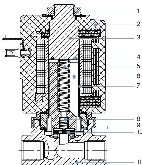
The physical construction of Burkert 20033682 incorporates materials selected for mechanical fatigue resistance and wide chemical compatibility across liquid and gaseous media:
| Item No. | Component | Material |
|---|---|---|
| 1 | Retaining Nut | Thick-film passivated steel (DIN 176) or stainless steel |
| 2 | Solenoid Coil | Chemically resistant epoxy resin |
| 3 | Stopper | Stainless steel 1.4113 (AISI 434) |
| 4 | Shading Ring | Silver (stainless steel body configuration) |
| 5 | Plunger Return Spring | Stainless steel 1.4310 (AISI 301) |
| 6 | Plunger / Core | Stainless steel 1.4113 (AISI 434) |
| 7 | Plunger Guide Tube | Stainless steel 1.4303 / AISI 305 / 308 (welded to stopper) |
| 8 | Lower Guide Spring | Stainless steel 1.4310 (AISI 301) |
| 9 | External Seal | PEEK / FKM |
| 10 | Valve Seat Seal | PTFE (pendulum seal design) |
| 11 | Valve Body | Stainless steel 1.4404 / AISI 316L (CF3M) |
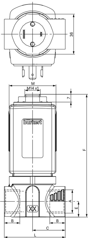
Burkert 20033682 utilizes the Type 6027 standard threaded inline body with connection size G 1/4 and 42 mm coil frame (Size K):
| Dimension Parameter | Symbol | Value (mm) |
|---|---|---|
| Process Connection Thread | A | G 1/4 |
| Thread Depth | B | 12.0 mm |
| Centerline to Rear Port Face | C | 27.5 mm |
| Centerline to Bottom Mounting Face | E | 10.0 mm |
| Overall Valve Height | F | 105.0 mm |
| Centerline to Front Port Face | H | 18.0 mm |
| Mounting Tapped Holes | J | M4 |
| Mounting Hole Thread Depth | K | 5.0 mm |
| Face-to-Face Body Length | L | 55.0 mm |
| Coil Width (Size K / 42 mm) | M | 42.0 mm |
| Coil Centerline Offset | N | 27.0 mm |
| Coil Body Height | O | 55.5 mm |
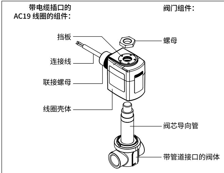
The valve utilizes a central bolted coil assembly (Size 42 mm / Type AC10/AC19) hermetically moulded in epoxy resin with Class H thermal insulation. The magnetic circuit is isolated from fluid media, enabling coil replacement without depressurizing the process piping.
Integrated Kick and Drop electronics feature an internal bridge rectifier and power switch. The coil draws 44 W for 500 ms during pull-in, followed by an immediate transition to 6.5 W holding power (5.5 W in thermal equilibrium). This double-coil control limits coil heating while supporting continuous duty (100% ED) across ambient temperatures up to +70 °C.
The electrical supply line is permanently encapsulated and exits perpendicular to the coil axis:
| Conductor Insulation Colour | Signal Assignment |
|---|---|
| Green-Yellow | Protective earth (PE) |
| Black (1) | Phase / L (+) |
| Black (2) | Neutral / N (-) |
Burkert 20033682 is approved for use in hazardous areas under European ATEX directive and international IECEx certification:
Pipeline Preparation
Prior to mounting, flush the pipeline thoroughly to prevent particulate debris from obstructing the 4.0 mm seat. Installing an upstream strainer with 0.2 mm to 0.4 mm mesh size is recommended to preserve seat integrity.
Hazardous Area Electrostatic Precautions
The encapsulated epoxy coil surface must be protected against electrostatic charges in explosive atmospheres. Clean the exterior surfaces using only a damp or anti-static cloth. Do not deploy the valve in processes involving strong electrostatic charge generation or pneumatic powder conveying.
Explore similar products in our catalog


