

PN16

BURKERT 20051938 (Type 8640) is a 7-bank modular pneumatic valve block with 33 mm station width, G 1/2 supply, G 1/4 working ports, 3/2 valve function, 2 to 8 bar pressure range, and single wiring execution.
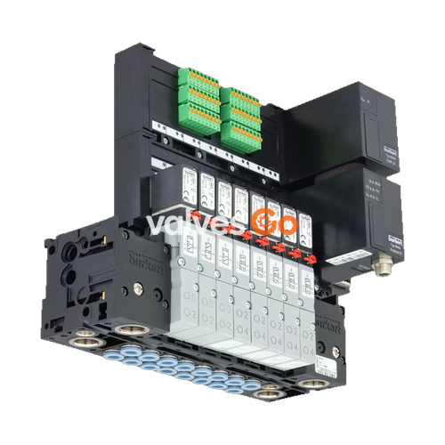
BURKERT 20051938 (Type 8640) is a 7-bank modular pneumatic valve block engineered for piloting pneumatic process valves and actuating pneumatic control circuits. Built with a 33 mm width per station configuration, this assembly integrates seven valve stations operating with 3/2-way valve functionality. The supply connection features a G 1/2 port, and all G 1/4 pneumatic working ports are arranged on the side opposite the supply feed. Operating across a nominal pressure envelope of 2.0 bar to 8.0 bar, the unit handles compressed dry air and neutral gases at medium temperatures from 0 °C to +50 °C within ambient operating limits of 0 °C to +55 °C.

Designed for standalone electrical architectures, article 20051938 operates via individual single wiring rather than internal backplane bus communications. The modular valve unit uses polyamide (PA) bodies and modules with NBR seals, mounted directly to standard DIN rail EN 50022 profiles (35 x 7.5 mm or 35 x 15 mm). It carries an ingress protection rating of IP20 as an open assembly, reaching IP65 protection when installed inside a sealed control cabinet or when each station is fitted with an approved cable plug such as Type 2516.
| Specification Parameter | Value / Execution |
|---|---|
| Article Number | 20051938 |
| Product Type | Type 8640 |
| Assembly Description | Valve block 8640 33mm 7-bank |
| Number of Valve Stations | 7-bank (7 valve slots) |
| Width per Station | 33 mm |
| Valve Circuit Function | 3/2-way valve function |
| Operating Pressure Range | 2.0 bar to 8.0 bar |
| Minimum Pressure Difference (Ports 1 to 3) | 2.0 bar |
| Medium Temperature Range | 0 °C to +50 °C |
| Ambient Operating Temperature | 0 °C to +55 °C |
| Storage Temperature | -40 °C to +55 °C (dry, dust-free) |
| Compressed Air Quality | ISO 8573-1:2010, Class 7.4.4 (5 µm filtration recommended) |
| Supply Port 1 (P) / Exhaust Port 3 (R) | G 1/2 |
| Working Ports 2 (A) / 4 (B) | G 1/4 (opposite of supply side) |
| Intermediate Supply Ports | 0 PCE |
| Digital Input Modules | 0 PCE |
| Modular Bus Variant | Without (due to single wiring) |
| Internal Bus Communication | Without (due to single wiring) |
| Operating Voltage | 24 V DC (±10% tolerance, 1 Vss residual ripple) |
| Operating Mode | Continuous operation (100% duty cycle) |
| Degree of Protection | IP20 (IP65 in closed cabinet or with Type 2516 plug) |
| Installation Type | Standard DIN rail EN 50022 (35 x 7.5 or 35 x 15) or direct wall mounting |
The Type 8640 modular block architecture consists of interconnected pneumatic modules locked mechanically by built-in latch hooks and tabs, eliminating intermediate external tubing between adjacent stations.
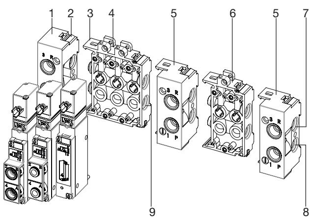
Sealing Integrity Warning
Crushed, dislodged, or unlubricated O-rings between sub-bases or beneath valve mounting interfaces cause immediate internal cross-channel leakage or external atmospheric leakage. Inspect all profile seals before snapping modules together.
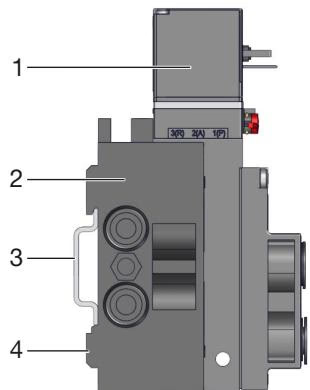
Article 20051938 supports rapid mounting on EN 50022 symmetrical DIN rails (35 x 7.5 mm or 35 x 15 mm) or direct flat-surface installation using M4 machine screws.
| Connection Size | Port Marking / Function | Recommended Torque | Maximum Permissible Torque |
|---|---|---|---|
| G 1/2 | Supply Port 1 (P), Exhaust Port 3 (R) | 6.0 to 10.0 Nm | 20.0 Nm |
| G 1/4 | Working Ports 2 (A), 4 (B) / Supply Options | 4.0 to 7.0 Nm | 20.0 Nm |
| G 1/8 | Working Ports / Single Outlets | 3.0 to 6.0 Nm | 7.0 Nm |
Piping Installation Precaution
Never use the solenoid coil or pilot actuator housing as a lever arm when tightening pneumatic fittings into the port threads. Support the polyamide block body directly with an open-end wrench.
Pneumatic supply lines must provide clean, dry compressed air compliant with ISO 8573-1:2010 Class 7.4.4. A filtration degree of 5 µm is recommended (maximum particle size 10 µm). A minimum differential pressure of 2.0 bar between supply port 1 (P) and exhaust port 3 (R) must be maintained at all times.
Hose lines attached to push-in connectors or threaded adapters must fulfill the following mechanical criteria:
| Hose Outer Diameter (OD) | Minimum Tensile Force (Polyamide PA) | Minimum Tensile Force (Polyurethane PU) |
|---|---|---|
| 3 mm (1/8") | 60 N | 25 N |
| 4 mm (5/32") | 70 N | 50 N |
| 6 mm (1/4") | 120 N | 100 N |
| 8 mm (5/16") | 170 N | 150 N |
| 10 mm (3/8") | 250 N | 200 N |
| 12 mm (1/2") | 300 N | 200 N |
| 16 mm (5/8") | 350 N | 300 N |
Article 20051938 uses single wiring connections directly to the coil contacts. Electrical control is established per station using cable plugs conforming to DIN EN 175301-803 Form C (such as Bürkert Type 2516).
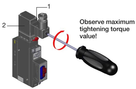
Continuous Operation Reliability
When valves remain energized or unswitched during extended operational standbys, Bürkert recommends scheduling 1 to 2 test switching cycles per day to maintain pilot mechanical responsiveness.
Before applying operating pressure, verify that all pneumatic lines are correctly routed and that the electrical manual override on each station is turned counterclockwise into its disengaged zero position.
| Fault Observed | Possible Cause | Corrective Action |
|---|---|---|
| Valve fails to switch | Insufficient or absent electrical operating voltage | Check supply wiring; ensure 24 V DC ±10% voltage is present at the coil plug terminals. |
| Valve fails to switch | Manual override engaged in locked position | Rotate manual override counterclockwise 90° back to the zero position. |
| Valve fails to switch | Supply pressure below operating threshold | Restore system pressure; maintain supply pressure between 2.0 bar and 8.0 bar. |
| Delayed switching or blow-off at exhaust | Insufficient air volume or restrictive upstream regulators | Install large-volume air lines and upstream regulators sized for peak consumption; maintain minimum 2 bar delta. |
| Delayed switching or blow-off at exhaust | Valve block not pressurized in de-energized home state | Apply pneumatic supply pressure to port 1 before actuating solenoid control signals. |
| Delayed switching or blow-off at exhaust | Exhaust silencers clogged, generating excessive back pressure | Clean or replace contaminated silencers; verify exhaust ducting diameter is unobstructed. |
| Delayed switching or blow-off at exhaust | Particulate contamination inside pilot or main seat | Purge exhaust ports with pulsed air or replace the affected valve seat insert. |
| External leakage between sub-bases | Missing, pinched, or damaged O-rings | Disassemble sub-block, replace defective inter-module O-rings, and re-engage latch hooks. |
| Leakage under valve base | Defective or misaligned flat gasket seal | Remove valve mounting screws, inspect flat gasket, replace if damaged, and retorque to 0.6 ±0.1 Nm. |
Explore similar products in our catalog


