

PN16

BURKERT 20060708 (Type 6757) is a direct-acting 2/2-way normally open Whisper flipper solenoid valve with media separation, PEEK body, FFKM seals, DN 2.0 mm, 24 V DC, and -1 to 10 bar operating pressure.
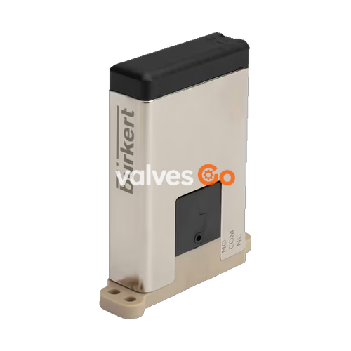
BURKERT 20060708 (Type 6757) is a direct-acting, media-separated 2/2-way Whisper flipper solenoid valve configured in Circuit Function B (normally open). Built with an 18 mm body width, high-performance PEEK housing, and perfluoroelastomer (FFKM) seals, it is engineered for critical fluid control in medical technology, in-vitro diagnostics (IVD), environmental analysis, and laboratory dosing systems. The valve combines a nominal diameter of DN 2.0 mm with vacuum to 10 bar operating pressure capability, offering rapid switching times of approximately 7 ms and acoustic switching emissions below 45 dB(A).
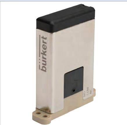
Type 6757 utilizes a direct-acting flipper switching mechanism isolated from the fluid path by an elastomer separating diaphragm. Fluid media contacts only the PEEK valve body and FFKM seals, protecting internal electromagnetic components from corrosion and preventing thermal transfer from the coil into sensitive working fluids.
Key design attributes supported by the manufacturer documentation:
| Parameter | Technical Specification |
|---|---|
| Circuit Function | 2/2-way solenoid valve, normally open (CF B / WW B) |
| Actuator Type | Direct-acting flipper mechanism |
| Orifice Size (DN) | 2.0 mm |
| Pressure Range | -1.0 bar to 10.0 bar (Vacuum to 10 bar) |
| Max. Differential Pressure | 10.0 bar |
| Nominal Voltage | 24 V DC |
| Voltage Tolerance | ±5% (including residual ripple) |
| Power Consumption | 4.5 W |
| Flow Value Kv (Water) | 0.080 m³/h (measured at +20 °C, 1 bar inlet, free outlet) |
| Flow Value Cv (Water) | 0.092 gpm |
| Nominal Flow QNn (Air) | 86 l/min |
| Switching Time | Open: ~7 ms / Close: ~7 ms |
| Switching Noise | < 45 dB(A) |
| Fluidic Body Material | PEEK (Polyetheretherketone) |
| Seal Material | FFKM (Perfluoroelastomer rubber) |
| Medium Temperature | +15 °C to +50 °C (cleaning cycles up to +90 °C, max. 30 min) |
| Ambient Temperature | +15 °C to +50 °C |
| Storage Temperature | -10 °C to +65 °C |
| Maximum Viscosity | 21 mm²/s |
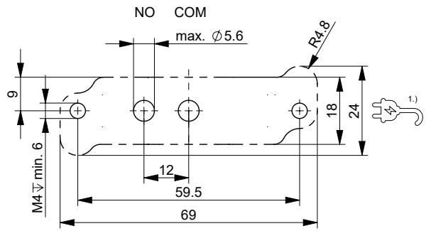
| Port Connection | Bürkert sub-base flange (18 x 69 mm, Version B1) |
| Electrical Connection | Rectangular plug grid 5.08 mm (Type 2505 compatible) |
| Degree of Protection | IP30 according to EN 60529 |
| Protection Class | Class III according to IEC 61140 / NEC Class II Power Supply |
Cleaning Cycle Conditions
The maximum valve body temperature must not exceed +110 °C. The valve must not be cycled during the +90 °C flushing procedure. Ensure adequate convective heat dissipation across the metallic surfaces during continuous operation.
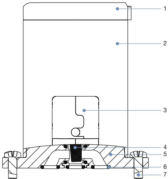
| Item No. | Component | Material | Wetted |
|---|---|---|---|
| 1 | Cover | Polyamide (PA) | No |
| 2 | Coil housing | Nickel-plated brass / steel | No |
| 3 | Valve housing | Polyphenylene sulfide (PPS) | No |
| 4 | Separating diaphragm | Perfluoroelastomer rubber (FFKM) | Yes |
| 5 | Valve body | Polyetheretherketone (PEEK) | Yes |
| 6 | Sub-base seal | Perfluoroelastomer rubber (FFKM) | Yes |
| 7 | Oval head screws | Stainless steel | No |
Wetted surfaces are restricted entirely to PEEK and FFKM, providing high chemical resistance against aggressive acids, bases, and organic solvents. Media compatibility can be verified using the Bürkert resistApp chemical resistance chart.
BURKERT 20060708 operates under Circuit Function B (normally open). In the de-energized state, the flow path between the normally open port (NO) and the common working port (COM) remains open. Energizing the coil shifts the flipper to seal the orifice seat, cutting off fluid transmission.
| Circuit Function | DN | NO Port Pressure | COM Port Pressure | Dummy Port | Max. Differential Pressure | Prescribed Flow Direction |
|---|---|---|---|---|---|---|
| CF B (2/2-way NO) | 2.0 mm | Vac to 10 bar | Vac to 10 bar | Blanked / Inactive | 10 bar | NO → COM |
Flow Direction and Pressure Limits
In vacuum operation and standard pressurized service, observe the prescribed flow direction from NO to COM. For incompressible media, line pressure surges (water hammer) must not exceed the maximum permissible differential pressure of 10 bar.
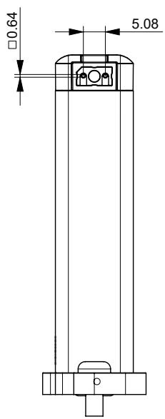
The sub-base configuration measures 18 mm in width with a 69 mm body pitch. Fastening is accomplished using two metric M4 x 10 stainless steel screws included in the scope of delivery.
When multiple Type 6757 valves are mounted side-by-side on a shared manifold block, thermal coupling limits the continuous operating envelope and pressure rating.
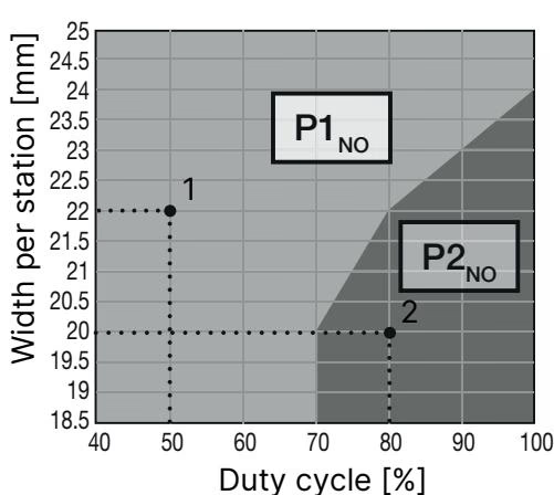
| Configuration | Orifice (DN) | Circuit Function | Area P1 (NO Port) | Area P2 (NO Port) | Duty Cycle Limit |
|---|---|---|---|---|---|
| Single Installation | 2.0 mm | CF B | Vac to 10 bar | - | 100% ED continuous |
| Block Structure (22 mm pitch) | 2.0 mm | CF B | Vac to 10 bar | - | 50% ED continuous |
| Block Structure (20 mm pitch) | 2.0 mm | CF B | - | Vac to 9 bar | 80% ED continuous |
| Block Structure General | 2.0 mm | CF B | - | - | 70% ED (max. 10 min duty cycle) |
Type 6757 requires a regulated 24 V DC supply voltage with a maximum voltage tolerance of ±5% (inclusive of residual ripple).
Electrical Polarity and Supply Quality
Correct electrical polarity is a mandatory prerequisite for proper switching operation. Do not operate the valve with unsmoothed, rectified alternating current. Ensure compliance with Protection Class III / NEC Class II power supply limits.
The valve features an integrated 2-pin terminal interface (pitch 5.08 mm) designed to accept Type 2505 rectangular cable plugs. Push-in cable connectors are not included with the bare valve and must be ordered separately.
Type 6757 is largely maintenance-free under normal operating conditions. Regular inspections should check for:
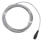
Type 2505 cable plugs provide the required IP30 electrical connection:
| Accessory Description | Configuration | Cable Length | Order Article No. |
|---|---|---|---|
| Cable plug 10 mm, 2-pin (Type 2505) | Straight | 0.3 m | 644068 |
| Cable plug 10 mm, 2-pin (Type 2505) | Straight | 0.6 m | 162144 |
| Cable plug 10 mm, 2-pin (Type 2505) | Straight | 3.0 m | 252572 |
| Cable plug 10 mm, 2-pin (Type 2505) | Straight | 5.0 m | 255194 |
| Cable plug 10 mm, 2-pin (Type 2505) | Angled | 3.0 m | 381035 |
Explore similar products in our catalog


