Transit-Time Ultrasonic

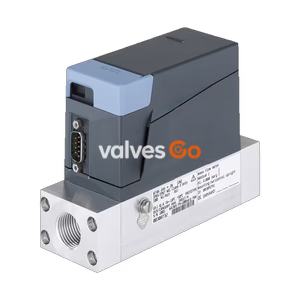
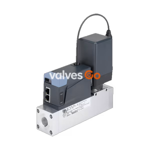
BURKERT Type 8745 Mass Flow Controller (MFC) and Meter (MFM) for gases. Features nominal flow ranges from 20 to 2500 lN/min, high accuracy, and Industrial Ethernet communication.
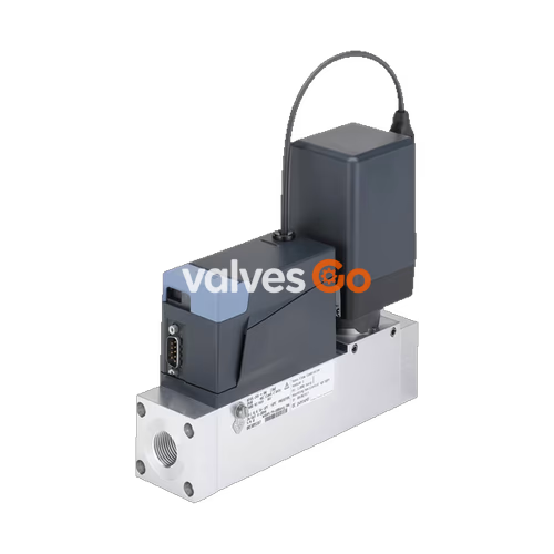
BURKERT Type 8745 is a mass flow controller (MFC) and mass flow meter (MFM) suitable for controlling the mass flow of large gas quantities. Type 8745 can be configured as MFM or MFC according to demand. Optionally, up to four calibration curves can be stored in the device. The thermal inline sensor located directly in the main gas stream achieves very fast response times with minimal pressure loss. As the actuator, a Bürkert direct-acting proportional valve guarantees high response sensitivity. As an MFC, Type 8745 is available in two variants: with an electromagnetic proportional valve and with an electromotive proportional valve. In addition to an analogue and an Industrial Ethernet variant, a Modbus RTU variant is also available.
| Property | Value |
|---|---|
| Seal Material | FKM or EPDM (depending on gas) |
| Housing Material | PC (polycarbonate) |
| Base Block Material | Aluminium or stainless steel 1.4404/316L |
| Wetted Parts (Sensor) | Stainless steel 1.4404/316L, Al₂O₃, PPS GF40, epoxy resin, silicon, silicon nitride |
| Operating Voltage | 24 V DC (±10% voltage tolerance, ±2% residual ripple) |
| Operating Medium | Neutral, pure gases (others on request) |
| Medium Temperature | -10 °C to +70 °C (-10 °C to +60 °C with oxygen) |
| Ambient Temperature | -10 °C to +50 °C (higher temperatures on request) |
| Degree of Protection | IP20 |
| Installation Position | Horizontal or vertical |
The MFC variant uses direct-acting proportional valves of the 287x series. These electromagnetic proportional valves are normally closed and stand for highest measuring accuracy and repeatability with settling times resp. response times of a few hundred milliseconds.
Type 8745 with electromotive proportional valve is especially suitable for applications with high inlet pressures of up to 22 bar or high flow rates (at a low pressure drop). The motor’s power consumption to hold a specific opening position is nearly zero, reducing plant energy consumption dramatically. Without electrical power, the valve remains in its current position.
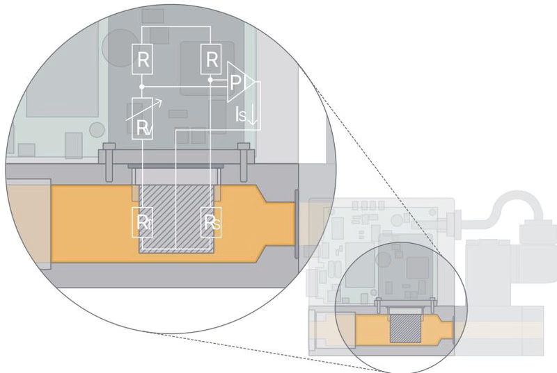
This sensor works as a hot-film anemometer in the CTA operational mode (Constant Temperature Anemometer). Two resistors with a precisely specified temperature coefficient located directly in the media flow and three further resistors are connected to form a measuring bridge. The first resistor in the gas flow measures the fluid temperature, while the second, low-value resistor is always heated just enough to keep it at a fixed, specified excess temperature with respect to the fluid temperature. The heating current required for this is a measure of the heat dissipation and represents the primary measured variable.
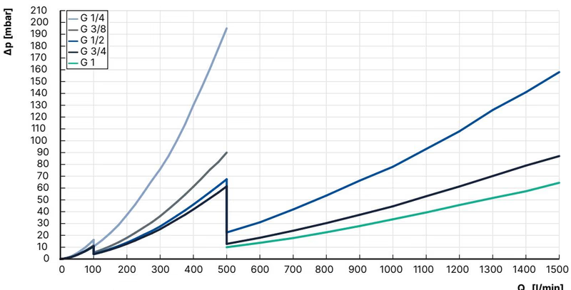
The diagram shows an example of the pressure loss curves with air flowing through. To determine the pressure loss of other gases, the corresponding air equivalent must first be calculated and the base block used for the other gas must be taken into account.
| Gas | Min. QN [l/min] | Max. QN [l/min] |
|---|---|---|
| Acetylene | 20 | 320 (from 65 l/min with air calibration) |
| Ammonia | 8 | 1000 |
| Argon | 20 | 1600 |
| Carbon dioxide | 20 | 800 |
| Air | 20 | 2500 |
| Methane | 20 | 1200 |
| Propane | 20 | 200 |
| Oxygen | 20 | 2500 |
| Nitrogen | 20 | 2500 |
(Note: All values refer to 1013.25 mbar abs and 273.15 K (0 °C).)
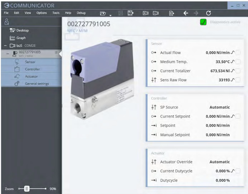
The Bürkert Communicator is the most important software component of the EDIP (Efficient Device Integration Platform). Various features of this universal tool simplify the configuration and parametrisation of devices equipped with a digital CANopen-based interface. The integrated graphical programming environment enables the creation of decentralised sub-system control functions.
If a device needs to be replaced, the memory card can be removed from the defective device and inserted into the new device. This transfers all data from the device to be replaced to the new device. The memory card is available as an accessory and must be ordered separately.
All Industrial Ethernet-based devices (except for the EtherCAT® protocol) from software version A.13.00.00 onwards have an integrated web server. The server can be accessed via a web browser when entering the device’s IP address (factory setting IP 192.168.1.100).
Electric shock due to electrical components
Touching live parts can result in severe electric shock. This can lead to serious personal injury or death.
Medium under pressure
Medium under pressure can seriously injure people. In the event of overpressure or pressure surges, the device or lines can burst. Pneumatic lines that are defective or not securely fastened can come loose and swing around.
Hot surfaces and fire hazard
The surface of the device can become hot with fast-switching actuators or with hot media.
Electrostatically sensitive components
The device contains electronic components that are susceptible to the effects of electrostatic discharging (ESD). Meet the requirements specified by EN 61340-5-1 to minimize or avoid the possibility of damage caused by a sudden electrostatic discharge.
Explore similar products in our catalog