

PN16

BURKERT 20070440 Type 8640 is a modular pneumatic valve island with 11 mm station width, G 1/4 supply ports, D6 push-in working ports, pneumatic HotSwap, and integrated check valves for 2.5 to 10 bar operation.
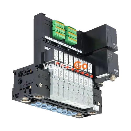
BURKERT 20070440 (Type 8640 revision 3) is a modular pneumatic valve island configured with an 11 mm station width and designed for DIN-rail mounting. Operating within a pressure range of 2.50 to 10.00 bar, the unit provides pneumatic automation control for filtered compressed air and neutral gases across medium temperatures from 0 °C to 50 °C and ambient temperatures from 0 °C to 55 °C. The manifold features G 1/4 supply connections, D6 bottom-oriented working ports on the pneumatic module, integrated check valves in exhaust ports 3 (R) and 5 (S), and pneumatic HotSwap capability in supply port 1 (P). It operates with single wiring without internal bus communication and provides an IP20 degree of protection.
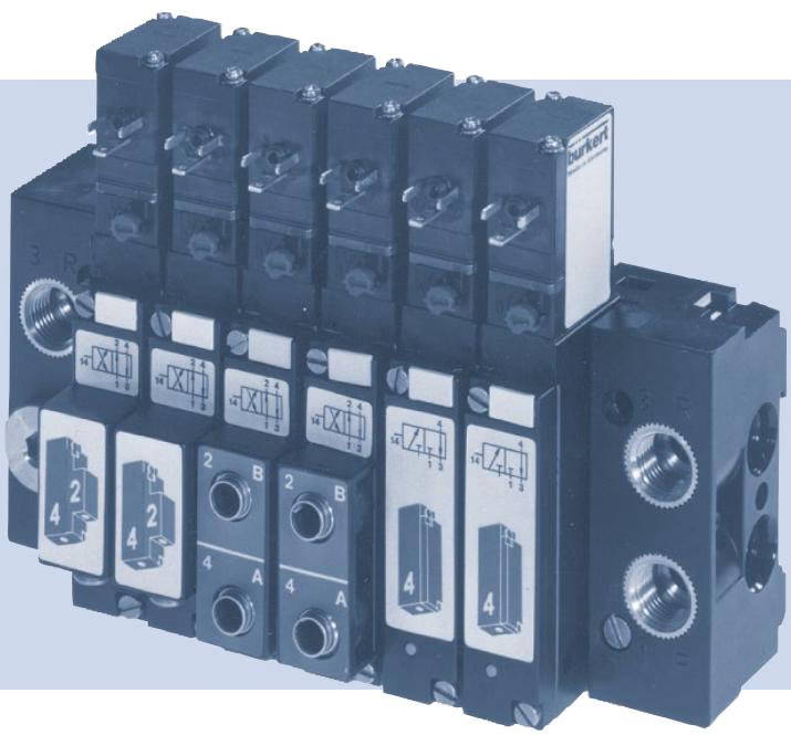
The valve island utilizes Type 5470 pilot-controlled solenoid valves mounted on modular base modules. Each valve assembly integrates a Type 6106 3/2-way pilot valve, valve body with diaphragm, seat seals, connection plates, and a lockable manual override.
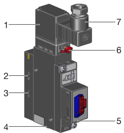
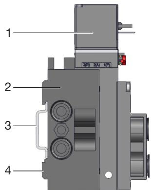
| Item | Designation |
|---|---|
| 1 | Pilot valve Type 6106 |
| 2 | Exhaust port 3 |
| 3 | Pressure port 1 |
| 4 | Working port 4 |
| 5 | Working port 2 |
| 6 | Manual override |
| 7 | Cable plug Type 2506 / 2516 |
To operate the valve manually, press the manual override down and turn it 90° clockwise until it stops. The mechanism locks into place and does not reset automatically.
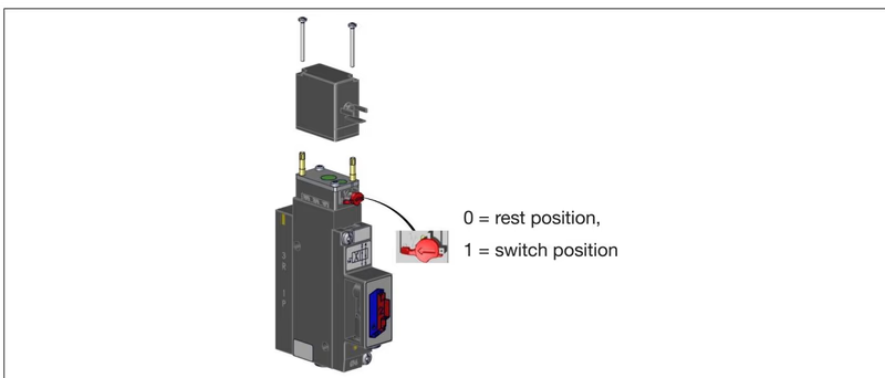
WARNING
Only operate the manual override when electrical power is switched off. Unlock the manual override to restore standard electrical control before system start-up.
| Connection Number | Designation |
|---|---|
| 1 | Pressure port (P) |
| 2 and 4 | Working ports (B and A) |
| 3 | Exhaust port (R) |
Type 8640 accommodates mixed valve population. Valves can be configured for specific circuit operations or converted between functions:
A 4/2-way valve can be converted to 3/2-way operation by closing one of the working ports with a dedicated stopper.
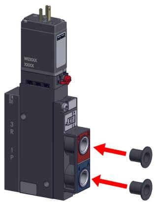
| Port 2 | Port 4 | Resulting Circuit Function |
|---|---|---|
| Closed | Open | Function C (3/2-way NC) |
| Open | Closed | Function D (3/2-way NO) |
| Parameter | Value |
|---|---|
| Operating medium | Filtered compressed air (particle size max. 10 μm, unlubricated or lubricated), neutral gases (5 μm filtering) |
| Operating pressure range | 2.50 bar to 10.00 bar (pilot pressure must be at least 70% of operating pressure) |
| Minimum pressure difference | 2 bar between port 1 and port 3 |
| Medium temperature | 0 °C to +50 °C (below 0 °C operation restricted to dried air) |
| Ambient temperature | 0 °C to +55 °C |
| Seal material | NBR |
| Supply connection | G 1/4 |
| Working ports | D6 push-in connectors, bottom-oriented |
| Electrical connection | Cable plug Type 2516 (DIN EN 175301-803 Form C) |
| Voltage tolerance | ±10% |
| Degree of protection | IP20 base island; IP65 when fitted with sealed cable plug Type 2516 |
| Integrated features | Check valves in 3 (R) and 5 (S); HotSwap in 1 (P) |
INFO
For functional reliability during continuous operation, Burkert recommends triggering at least 1 to 2 switching cycles per day during extended idle times.
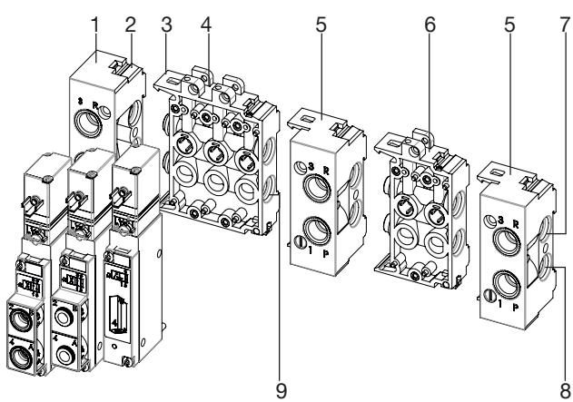
| Item | Designation |
|---|---|
| 1 | Left connection module |
| 2 | Latch tab |
| 3 | Latch hook |
| 4 | Base modules (3-fold) |
| 5 | Right connection module |
| 6 | Base modules (2-fold) |
| 7 | Exhaust channel 3 (R) |
| 8 | Supply channel 1 (P) |
| 9 | O-ring |
The solenoid coil can be rotated 180° on the valve body to suit space constraints:
DANGER
Ensure the protective earth contact of the coil is firmly connected to the valve body. Verify electrical continuity between the ground pin and the valve body before applying voltage.
| Port Size | Function | Recommended Torque [Nm] | Maximum Torque [Nm] |
|---|---|---|---|
| G 1/4 | Supply port P, exhaust R/S | 4 to 7 | 20 |
| G 1/8 | Supply P, exhaust R/S, outlets A/B | 3 to 6 | 7 |
Ensure supply lines are flushed clean before connection. Push pneumatic tubing into the D6 push-in connectors until it seats against the internal stop.
| Hose Outer Diameter (OD) | 3 mm | 4 mm | 6 mm | 8 mm | 10 mm | 12 mm | 14 mm | 16 mm |
|---|---|---|---|---|---|---|---|---|
| Min. Tensile Force (PA tubing) [N] | 60 | 70 | 120 | 170 | 250 | 300 | 300 | 350 |
| Min. Tensile Force (PU tubing) [N] | 25 | 50 | 100 | 150 | 200 | 200 | 250 | 300 |
TIP
If retention issues occur with softer polyurethane tubing, insert support sleeves (ID 20099400) into the tube end to reinforce joint sealing and mechanical retention.
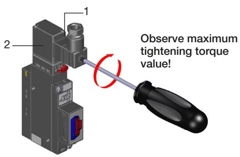
The unit is wired individually using cable plug Type 2516 (or DIN EN 175301-803 Form C connectors). Fasten the cable plug retaining screw to a maximum torque of 0.3 Nm, ensuring the flat seal is properly compressed.
| Test Parameter | Specification Limit |
|---|---|
| Protective conductor resistance | Maximum 0.1 Ω |
| Test voltage | 12 V |
| Test current | 1 A |
For bistable impulse coil variants, maintain a pulse duration of at least 50 ms and observe coil polarity markings:
| Pin Polarity | Pilot Valve State | Effect (WWG) | Effect (WWC) |
|---|---|---|---|
| (+) on Pin 2, (-) on Pin 1 | Pilot valve opens | 1 connects to 3, 2 connects to 3 | 1 connects to 4 |
| (+) on Pin 1, (-) on Pin 2 | Pilot valve closes | 1 connects to 2, 4 connects to 3 | 4 connects to 3 |
Prior to initial power-up, confirm the following steps:
| Symptom | Probable Cause | Corrective Action |
|---|---|---|
| Valves fail to switch | Operating voltage absent or out of tolerance | Check power supply and wiring against type label rating. |
| Manual override locked in manual state | Turn override mechanism 90° back to the zero position. | |
| Supply pressure insufficient (< 2.5 bar) | Increase upstream regulator capacity; maintain ≥ 2.5 bar. | |
| Delayed switching or continuous venting | Supply volume inadequate | Ensure unrestricted supply pipe cross-section. |
| Valves energized prior to pressure build-up | Pressurize manifold before applying electrical control signals. | |
| Silencer clogged or undersized | Clean or replace silencer; reduce back pressure. | |
| Particulate contamination in pilot or seat | Cycle exhaust ports with pressure pulses or replace valve unit. | |
| Leakage between valve modules | Missing or pinched O-rings | Disassemble block, inspect seals, replace damaged O-rings. |
Store the unit in a clean, dust-free environment between -40 °C and +55 °C with all port caps fitted. Dispose of electrical modules and plastic components in accordance with WEEE directives and local electronic waste regulations.
Explore similar products in our catalog


