

PN16

BURKERT 20073326 (Type 8647 AirLINE SP) 20-bank valve island features 20x 2x3/2 NC valves, 11 mm width, G 1/4 supply, D6 working ports, HotSwap, and ATEX/IECEx Zone 2 approval.
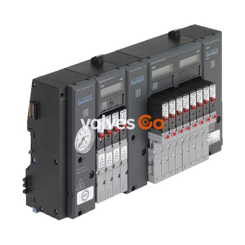
BURKERT 20073326 (Type 8647 AirLINE SP) is a modular electropneumatic automation system engineered for seamless mechanical and electrical integration with the Siemens SIMATIC ET 200SP and SIMATIC ET 200SP HA distributed I/O systems. Built in a Revision 2 (REV.2) hardware architecture with an 11 mm width per station, this fully assembled 20-bank valve terminal houses 20 Type 6524 double solenoid valves. Each valve station provides two independently actuated 3/2-way normally closed valves (Circuit Function C C), delivering a total of 40 discrete pneumatic control channels in a high-density footprint.
Primary air supply and common exhaust lines interface through G 1/4 female threaded ports on the connection units, while working connections emerge as bottom-oriented D6 push-in couplings. Pneumatic stability across the 40 valve functions is sustained by an integrated PSU-M intermediate feed unit. The assembly incorporates check valves within exhaust ports 3 (R) and 5 (S) to eliminate back-pressure switching interference, alongside integrated P-channel HotSwap shut-off seats that permit single-valve replacement while the remaining valve block remains fully pressurized. BURKERT 20073326 carries ATEX and IECEx explosion-proof certification for Category 3G equipment (Zone 2, Ex ec IIC T4 Gc) and operates across 2.5 to 10.0 bar within an ambient temperature range of 0 °C to +55 °C.
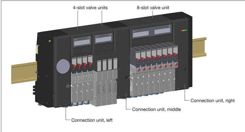
Type 8647 combines electrical bus communications and pneumatic power amplification on a common DIN rail. The 20073326 configuration is assembled from four interconnected functional modules:
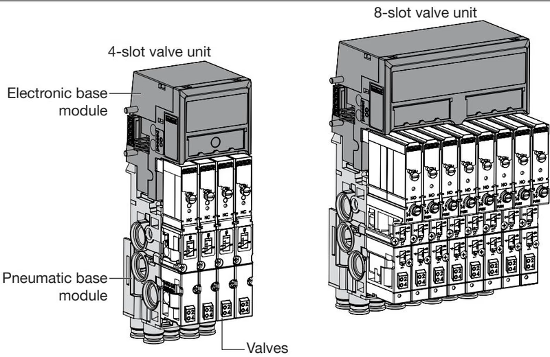
BURKERT 20073326 incorporates REV.2 engineering improvements across all pneumatic sub-assemblies:
| Feature | Parameter Specification |
|---|---|
| Product Identifier | BURKERT Type 8647 AirLINE SP (Article 20073326) |
| Hardware Generation | Revision 2 (REV.2) |
| Station Configuration | 20 valve slots, 11 mm width per station (20-bank) |
| Integrated Valve Function | 20x (2x 3/2-way) Circuit Function C C (normally closed) |
| Total Controlled Channels | 40 independent pneumatic working outputs |
| Operating Pressure Range | 2.5 bar to 10.0 bar (gauge pressure) |
| Flow Rate ($Q_{\text{Nn}}$ air) | 300 l/min (measured at +20 °C, 6 bar inlet, 1 bar $\Delta p$; ~20% reduction with P-shutoff) |
| Nominal Operating Voltage | 24 V DC (±10%), max residual ripple 2.4 Vss, SELV/PELV |
| Power Consumption per Valve | 2x 0.8 W (with electronic power reduction) |
| Current Draw per Valve | 40 mA inrush; 28 mA holding current after 120 ms |
| Protection Class | III according to DIN EN 61140, VDE 0140 |
| Ingress Protection | IP20 according to EN 60529 (IP65 in closed control cabinet) |
| Operating Medium | Lubricated or non-lubricated dry compressed air, neutral gases (5 µm filtration) |
| Compressed Air Quality | ISO 8573-1:2010, Class 7.4.4 |
| Medium Temperature | 0 °C to +50 °C |
| Ambient Temperature | 0 °C to +55 °C (storage: -20 °C to +60 °C) |
| Relative Humidity | 75% average, 85% peak, non-condensing |
| Supply Port Connections (1, 3, 5) | G 1/4 female thread |
| Auxiliary Pilot / Exhaust Port (X) | M5 thread |
| Working Connections (2, 4) | D6 push-in tube coupling, bottom module orientation |
| Intermediate Feed Modules | 1 PCE (PSU-M G 1/4) |
| HotSwap Functionality | Integrated mechanical P-shutoff valve per slot |
| Exhaust Check Valves | Integrated non-return valves in channels 3 (R) and 5 (S) |
| Explosion Protection | ATEX: BVS 18 ATEX E 078 X; IECEx: IECEx BVS 18.0068 X; II 3 G Ex ec IIC T4 Gc |
| Control Cabinet Requirement | Enclosure with minimum IP54 ingress protection |
Air supply and exhaust piping connect directly to the PSU connection blocks. The 20073326 terminal utilizes G 1/4 ports for main supply pressure 1 (P) and exhaust deaeration channels 3 (R) and 5 (S).
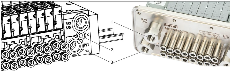
| Port Identification | Marking | Fluidic Function | Thread / Connector Size |
|---|---|---|---|
| 1 | P / 1 | Compressed air supply | G 1/4 female |
| 2 | X | Auxiliary pilot air / Pilot exhaust | M5 female |
| 3 | R / 3, S / 5 | Common system exhaust | G 1/4 female |
| Working Outputs | 2 (A), 4 (B) | Actuator working lines | Push-in D6 mm (bottom) |
Exhaust Air Management
To prevent back-pressure accumulation and unintended valve switching, exhaust lines must be routed through silencers of adequate volume or ducted outside the cabinet using unrestricted tubing cross-sections. Do not plug exhaust ports 3, 5, or pilot exhaust X.
When deploying Type 6524 2x3/2-way double valves, an intermediate supply module (PSU-M) is required after every 16 valve functions (8 double valve slots) to avoid pressure drop during simultaneous actuations. Because BURKERT 20073326 houses 20 double valves (40 valve functions), 1 PCE intermediate feed unit (PSU-M) is factory-configured into the valve block array.
Each Type 6524 double valve contains two independently actuated 3/2-way valves corresponding to two separate working ports on the pneumatic base module:
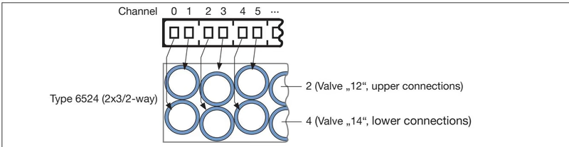
| Port Size | Function | Recommended Torque | Maximum Torque |
|---|---|---|---|
| G 1/4 | P (Supply), R/S (Exhaust) | 4.0 Nm to 7.0 Nm | 20.0 Nm |
| M5 | X (Pilot exhaust / Aux air) | 1.0 Nm to 1.2 Nm | 3.0 Nm |
| M7 | AirLINE Quick Push-in fittings | 1.75 Nm to 2.25 Nm | 4.0 Nm |
| M2 | Type 6524 double valve fastening screws | 0.15 Nm to 0.20 Nm | 0.25 Nm |
Each valve slot on the 20073326 terminal is equipped with a Type 6524 2x3/2-way pilot valve. The pilot stages consist of Type 6144 flipper solenoid actuators directing air to pneumatic poppet seat amplifiers. This design delivers rapid cycle response and high holding force at a static holding power of only 0.8 W per coil.
Type 8647 docks directly to the backplane bus of Siemens SIMATIC ET 200SP or ET 200SP HA modular peripheral systems without external intermediate wiring. Electrical load voltage (24 V DC) and backplane communication are established automatically as modules click together along the DIN rail.
Other field devices -> PROFINET IO -> I/O -> Pneumatics (Burkert).Power Bus Separation
A light-colored Siemens BaseUnit (BU...D or BU...D/T) must be installed immediately to the left of the valve block to feed a separate 24 V DC load voltage group. This arrangement is mandatory when operating in ET 200SP HA stations to prevent backplane voltage drop.
Each electronic base module monitors individual channel electrical integrity and backplane communication:
0x02F3 (Wire break) or 0x02F4 (Short circuit) to the PLC.0x11 (No supply voltage) is generated. Valves switch off into their safe home position.Type 8647 supports multiple distinct electrical shutdown configurations for functional safety implementations:
Safety Assessment Responsibility
Manual override operation overrides electrical safety shutdown commands. For safety-critical installations, either protect manual overrides against unintentional manipulation or utilize valve variants without manual override (Article 300818). Ensure exhaust lines vent unrestricted.
BURKERT 20073326 ships fully pre-assembled on a transport rail. Before mounting in the control cabinet:
Thanks to integrated P-shutoff seats within the pneumatic base module, Type 6524 valves can be replaced without depressurizing the main air header:
Revision Compatibility Limit
REV.1 and REV.2 single valves possess different mechanical flange geometries and cannot be interchanged. REV.2 double valves (Type 6524 2x3/2) require matching REV.2 pneumatic base units with FM20 profile gaskets.
Working ports use D6 push-in couplings designed for calibrated polyamide (PA) or polyurethane (PU) tubing:
| Item Description | Revision / Specification | Packaging Unit | Article No. |
|---|---|---|---|
| Replacement Valve Type 6524 2x3/2 NC | 24 V DC, 2.5–10 bar, manual override, FM20 | 1 pc | 204710 |
| Replacement Valve Type 6524 2x3/2 NC | 24 V DC, 1–10 bar, aux pilot air, manual override | 1 pc | 300817 |
| Replacement Valve Type 6524 2x3/2 NC | 24 V DC, 2.5–10 bar, no manual override | 1 pc | 300818 |
| Valve Profile Gaskets FM20 | For Type 6524 2x3/2-way double valves | 12 pcs | 20016305 |
| Module Gaskets MP16 | Between REV.2 base modules | 4 pcs | 20024339 |
| Blanking Cover Plate | For Type 6524 2x3/2 double valve slot (REV.2) | 1 pc | 661092 |
| Electrical Connection Cover | For unused electronic module sockets | 1 pc | 653670 |
| Left Interface Unit Set | Interface adapter to Siemens ET 200SP BaseUnit | 1 set | 20029826 |
| Push-In Connector D6 mm (Brass) | Nickel-plated brass tube fittings | 8 pcs | 20024340 |
| Push-In Connector D6 mm (Stainless) | Stainless steel 1.4401 tube fittings | 8 pcs | 20024341 |
| Intermediate Supply Unit PSU-M | G 1/4 intermediate feed module | 1 pc | 20030063 |
Explore similar products in our catalog


