

PN16

BURKERT 20074352 (Type 8652) AirLINE is a 4-bank pneumatic valve island with stainless steel AirLINE Quick plate, Industrial Ethernet RJ45 connectivity, 8 digital inputs, and HotSwap capability.
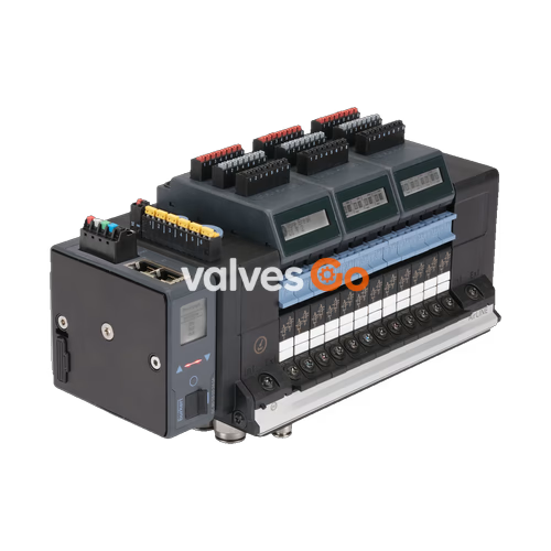
BURKERT 20074352 (Type 8652) AirLINE is a 4-bank pneumatic valve island engineered for process automation environments, featuring an integrated stainless steel AirLINE Quick adapter plate and Industrial Ethernet communication. The assembly accommodates 4 valve slots fitted with four 2x 3/2-way normally closed (circuit function C) pilot-operated valves, providing 8 independently controlled pneumatic outputs within an 11 mm station width format. Operating over a pressure range from -1.0 to 10.0 bar with internal pilot feed at 3 to 10 bar, the unit provides a nominal airflow rate of 310 l/min.
Equipped with dual RJ45 ports supporting multiprotocol Industrial Ethernet (PROFINET IO, EtherNet/IP, Modbus TCP, EtherCAT, and CC-Link IE Field Basic), the valve terminal integrates an 8-point digital input module directly on the sub-base. It incorporates process security features including integrated check valves in the exhaust channels 3 (R) and 5 (S) to suppress pressure peaks, as well as a pneumatic HotSwap mechanism in pressure supply port 1 (P) that allows replacing individual valves during live operation.

| Specification Parameter | Technical Value |
|---|---|
| Model Order Number | 20074352 |
| Base Type Family | 8652 AirLINE |
| Number of Valve Slots | 4 stations (expandable series architecture up to 24 slots) |
| Pre-installed Valve Configuration | 4x 2x 3/2-way Solenoid Valve Type 6534 (CF-C, normally closed) |
| Width per Valve Station | 11 mm |
| Operating Pressure Range | -1.0 bar to 10.0 bar (vacuum to 10 bar) |
| Pilot Pressure Range | 3 bar to 10 bar (internal auxiliary pilot air) |
| Flow Rate $Q_{\text{Nn}}$ (Air) | 310 l/min (measured at +20 °C, 6 bar inlet, $\Delta p = 1$ bar) |
| Flow Rate with HotSwap Function | Approx. 3% flow reduction |
| Operating Voltage | 24 V DC (±10%), residual ripple 1 Vss |
| Power Consumption per Valve | 0.7 W nominal (0.175 W after internal power reduction) |
| Current Draw per Valve | 29 mA nominal (10 mA after internal power reduction) |
| Operating Mode | Continuous operation (100% duty cycle) |
| Protection Class | III according to DIN EN 61140, VDE 0140 |
| Degree of Protection | IP20 standalone; IP65 inside closed cabinet with AirLINE Quick plate |
| Operating Medium | Oil-free or lubricated dry compressed air, neutral gases (5 µm filtration recommended) |
| Air Quality Standard | ISO 8573-1:2010, Class 7.4.4 |
| Ambient and Medium Temperature | -10 °C to +55 °C |
| Storage Temperature | -20 °C to +60 °C |
| Type Rating (NEMA 250) | Type 4X in closed enclosures with stainless steel version |
BURKERT 20074352 is configured with the AirLINE Quick adapter interface constructed from 1.4301 (304) stainless steel and fitted with 1.4401 (316) stainless steel push-in fittings. This design enables the terminal to mount flush into the control cabinet floor or wall cutout, projecting the pneumatic connections directly outside the cabinet enclosure.
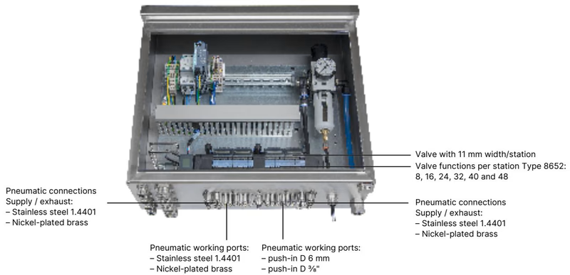
The 4 valve slots on the 20074352 assembly are factory-populated with four Type 6534 dual 3/2-way normally closed valves (Circuit Function C / CF C), totaling 8 independently actuatable pilot valves. Each valve slice utilizes a 6164 pilot valve operating a servo-controlled spool.
| Valve Position | Circuit Function Code | Valve Construction | Normal State | Nominal Diameter | Switching Time Opening | Switching Time Closing |
|---|---|---|---|---|---|---|
| Position 1 | 2x 3/2-way (CF-C) | Servo-controlled with manual override | Normally closed | 4 mm | 15 ms | 15 ms |
| Position 2 | 2x 3/2-way (CF-C) | Servo-controlled with manual override | Normally closed | 4 mm | 15 ms | 15 ms |
| Position 3 | 2x 3/2-way (CF-C) | Servo-controlled with manual override | Normally closed | 4 mm | 15 ms | 15 ms |
| Position 4 | 2x 3/2-way (CF-C) | Servo-controlled with manual override | Normally closed | 4 mm | 15 ms | 15 ms |
Manual Overrides
Each valve slice includes latching and spring-return manual overrides for local commissioning and manual testing.
The terminal incorporates an ME43 Industrial Ethernet communication module with two RJ45 female connectors (labeled X1 and X2), providing line and ring network topology support across multiple industrial protocols:
| Pin Number | Signal Assignment |
|---|---|
| 1 | TX+ (Transmit Data +) |
| 2 | TX- (Transmit Data -) |
| 3 | RX+ (Receive Data +) |
| 4 | N.C. (Not connected) |
| 5 | N.C. (Not connected) |
| 6 | RX- (Receive Data -) |
| 7 | N.C. (Not connected) |
| 8 | N.C. (Not connected) |
Power supply inputs are divided into two isolated terminals on the base interface board to separate communication and pilot valve power circuits:
| Terminal Block | Pin / Clip | Wire Color | Signal Assignment | Conductor Cross-Section |
|---|---|---|---|---|
| 5-Pin Spring Terminal (Logic/Bus/Display) | 1 | Red | +24 V DC | $\le 1.5\text{ mm}^2$ |
| 2 | White | CAN_H (büS connection) | $\le 1.5\text{ mm}^2$ | |
| 3 | Green | Shielding | $\le 1.5\text{ mm}^2$ | |
| 4 | Blue | CAN_L (büS connection) | $\le 1.5\text{ mm}^2$ | |
| 5 | Black | GND (0 V DC) | $\le 1.5\text{ mm}^2$ | |
| 2-Pin Spring Terminal (Pneumatic Valves) | 1 | Red | AUX +24 V DC | $\le 1.5\text{ mm}^2$ |
| 2 | Black | GND (0 V DC) | $\le 1.5\text{ mm}^2$ |
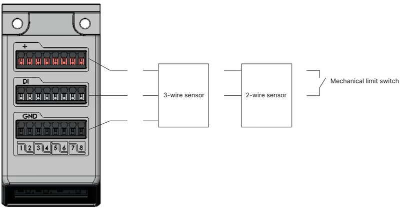
BURKERT 20074352 integrates an 8-channel electronic input module (8DI) to capture end-position feedback directly from process actuators, limit switches, and inductive proximity switches.
| Parameter | Value / Characteristic |
|---|---|
| Number of Digital Inputs | 8 channels |
| Sensor Voltage Supply | 24 V DC via electronic module (max. 30 mA per input) |
| Compatible Sensor Types | 2-wire sensors, 3-wire sensors (10–30 V), mechanical limit switches |
| Switching Thresholds | $V_{\text{OFF}} = 0\text{ to }5\text{ V}$, $V_{\text{ON}} = 10\text{ to }30\text{ V}$ |
| Input Current at $V_{\text{ON}}$ | Max. 5.7 mA per channel (typical at 24 V DC) |
| Input Impedance | $> 4\text{ k}\Omega$ |
| Galvanic Isolation | None (all channels share common reference ground) |
| Diagnostic Capabilities | Wire-break detection (2-wire sensors); short-circuit detection (3-wire sensors) |
| Maximum Wiring Length | $< 30\text{ m}$ (wire gauge $\le 1.5\text{ mm}^2$) |
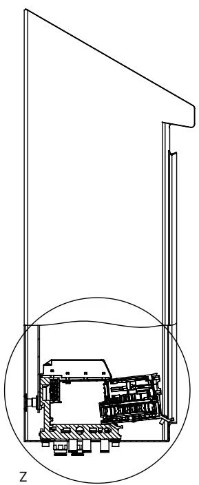
The supply channel 1 (P) features integrated non-return valves behind each valve station. When a solenoid valve is unscrewed and lifted from the manifold, the pneumatic seat seals immediately. This prevents pressure drop in adjacent valve stations, allowing maintenance and valve replacement while the pneumatic system remains pressurized.
Cabinet Clearance
To enable unimpeded replacement of valves via the HotSwap function, maintain minimum clearance to the front edge and side walls of the control cabinet as defined in the Type 8652 operating manual.
Integrated check valves inside exhaust ducts 3 (R) and 5 (S) prevent back-pressure propagation. When multiple valves exhaust simultaneously, exhaust pressure surges cannot actuate spring-return single-acting cylinders or cause unplanned actuator movements.
Hazardous Area Special Conditions
When installed in ATEX/IECEx Zone 2 or Class I, Div 2 hazardous environments (PX68/PU17 approvals), HotSwap operations and terminal block disconnections must only be performed when the system is fully de-energized or after confirming that no explosive atmosphere is present.
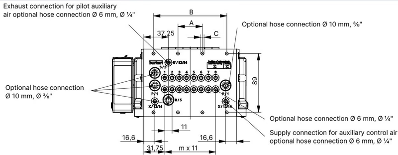
Dimensions for the 4-fold basic variant of Type 8652:
| Manifold Variant | Dimension A [mm] | Dimension B [mm] | Mounting Fasteners (C) | Module Pitch Index m | Module Pitch Index n |
|---|---|---|---|---|---|
| 4-fold (Article 20074352) | 66 mm | — (not applicable) | 4x M5 | 3 | 1 |
| 8-fold (Reference) | 35 mm | 111 mm | 8x M5 | 7 | 2 |
| 12-fold (Reference) | 77 mm | 154 mm | 10x M5 | 11 | 3 |
Standard DIN rail mounting according to EN 50022 ($35\times 7.5\text{ mm}$ or $35\times 15\text{ mm}$) is supported in addition to direct floor/wall cutout installation via the AirLINE Quick plate.
| Component Description | Reference / Article No. | Notes |
|---|---|---|
| Replacement Valve Type 6534: 2x 3/2-way CF-C (24 V DC) | Article no. 301374 (REF 296031) | Includes mounting screws; identical to the pre-installed valves on 20074352 |
| Replacement Valve Type 6534: 2x 3/2-way CF-D (normally open) | Article no. 301375 (REF 296032) | Optional alternate circuit function |
| Replacement Valve Type 6534: 5/2-way CF-H | Article no. 301376 (REF 296033) | 5/2-way monostable configuration |
| Dummy / Blanking Plate Valve | Article no. 335779 (REF 327614) | Used to cover unpopulated valve slots |
| 5-Pin Spring-Loaded Terminal Block | Article no. 920180 | Logic, display, and communication supply connector |
| 2-Pin Spring-Loaded Terminal Block | Article no. 920442 | Auxiliary power connector for pneumatic valves |
| Screw Set M5 x 10 A2 DIN 6912 | Article no. 308661 | Pack of 10 screws for securing valve terminal to base |
| AirLINE Quick Height Adapter (4-fold) | Article no. 60031491 | Height leveling plate without intermediate feed |
| AirLINE Quick Retaining Plate (4-fold) | Article no. 60005571 | Exterior cabinet clamping plate for 4-fold variant |
| USB-büS Interface Set 1 (Type 8923) | Article no. 772426 | For PC parameterization via Bürkert Communicator (Type 8920) |
Explore similar products in our catalog


