

PN16

Burkert 20075853 Type 8647 AirLINE SP is a 12-bank 11 mm electropneumatic valve island for Siemens SIMATIC ET 200SP/SP HA with G 1/4 supply ports, D6 push-in ports, HotSwap P-shutoff, and 2.5-10 bar operating pressure.
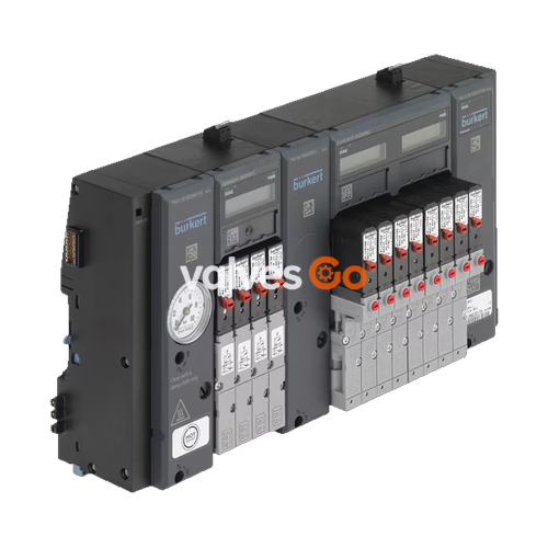
Burkert 20075853 Type 8647 AirLINE SP is a modular electropneumatic automation system and 12-bank pneumatic valve island engineered for direct integration into Siemens SIMATIC ET 200SP and SIMATIC ET 200SP HA distributed I/O systems. Based on an 11 mm width per station, this pre-assembled valve block configuration provides 12 valve slots with bottom-oriented D6 mm push-in working connections and G 1/4 pneumatic supply and exhaust connections. The unit operates within a nominal pressure range of 2.5 bar to 10.0 bar and a medium temperature span of 0 °C to +50 °C, using dried, oil-free or lubricated compressed air filtered to 5 µm in accordance with ISO 8573-1:2010 Class 7.4.4. Built to Revision 2 (REV.2) mechanical standards, Burkert 20075853 features integrated pneumatic HotSwap check valves in channel 1 (P) for replacement of individual valves while pressurized, alongside integrated non-return check valves in exhaust channels 3 (R) and 5 (S) to prevent spurious actuator switching caused by exhaust line pressure spikes.
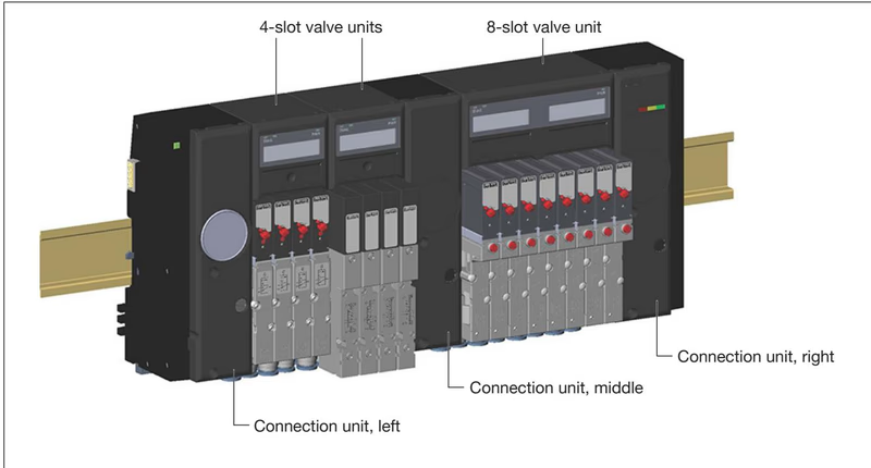
Burkert Type 8647 operates as an integral component of the Siemens distributed peripheral system. The valve block connects mechanically and electrically to the standard rail and interfaces directly with the backplane bus of the SIMATIC ET 200SP or SIMATIC ET 200SP HA interface modules (IM 155-6 PN or IM 155-6 DP). Process, configuration, and diagnostic data are transferred cyclically via PROFINET IO or PROFIBUS DP without requiring discrete point-to-point field wiring between the PLC output cards and pilot solenoid coils.
+-----------------------------------------------------------------------------------------+ | Siemens SIMATIC ET 200SP / ET 200SP HA | | +----------------+ +-----------------+ +------------------------------------------+ | | | Interface Mod. | | Siemens I/O | | Burkert Type 8647 AirLINE SP (20075853) | | | | (IM 155-6 PN) | | BaseUnits | | +--------+ +--------------+ +----------+ | | | | | | (Power Supply) | | | PSU-L | | 12x Valve | | PSU-R | | | | | | | BU...D / BU...D/T| | (G 1/4) | | Slots (11mm) | | (G 1/4) | | | | +-------+--------+ +--------+--------+ +----+---+ +-------+------+ +----+-----+ | | +----------|--------------------|----------------|-------------|-------------|------------+ | | | | | +== Backplane Bus ===+================+=============+=============+
Software integration is supported through multiple configuration options:
| Specification | ET 200SP Station | ET 200SP HA Station |
|---|---|---|
| Maximum modules per island | 64 modules (I/O modules + valve units) | 56 modules (I/O modules + valve units) |
| Multiple valve blocks per station | Yes (requires new BaseUnit power feed) | No (maximum 1 valve block per station) |
| Valve block position on station | Flexible; Siemens I/O modules allowed to the right | Rightmost position only; no I/O modules to the right |
| BaseUnit upstream of valve block | Recommended (BU...D or BU...D/T) | Mandatory (BU...D or BU...D/T with cover) |
| AirLINE Quick base adaptation | Permitted (subject to baseplate sizing) | Not supported by design |
| Parameter | Technical Specification |
|---|---|
| Article number | 20075853 |
| Model designation | Valve island 8647 11 mm 12-bank |
| Width per station | 11 mm per valve position |
| Total valve slots | 12 valve slots |
| Hardware generation | Revision 2 (REV.2) |
| Valve population | Mixed valve population (3/2-way function) |
| Supply connection (1/P) | G 1/4 female thread |
| Exhaust connections (3/R, 5/S) | G 1/4 female thread |
| Working connection (2/A, 4/B) size | D6 mm push-in coupling |
| Working connection orientation | Bottom face of pneumatic base module |
| Operating pressure range | 2.5 bar to 10.0 bar (gauge pressure) |
| Medium temperature | 0 °C to +50 °C |
| Ambient operating temperature | 0 °C to +55 °C |
| Storage temperature | -20 °C to +60 °C |
| Permissible relative humidity | 75% average, 85% occasional, non-condensing |
| Operating medium | Dry compressed air, neutral gases, lubricated or non-lubricated (ISO 8573-1:2010 Class 7.4.4, 5 µm filter) |
| Integrated P HotSwap function | Yes (check valve in port 1 of pneumatic base module) |
| Integrated exhaust check valves | Yes (ports 3/R and 5/S) |
| Nominal flow rate QNn (air) | 300 l/min (reduced by approx. 20% with active P shut-off) |
| Operating voltage | 24 V DC (±10%, residual ripple max 2.4 Vss, SELV/PELV) |
| Power consumption per single valve | 0.8 W (continuous operation, 100% ED) |
| Power consumption per double valve | 2 × 0.8 W (with integrated power reduction) |
| Degree of protection | IP20 (according to EN 60529); up to IP65 in sealed enclosure |
| Mounting arrangement | DIN rail (standard mounting rail, horizontal or vertical) |
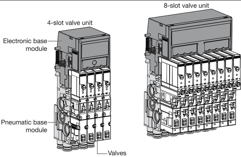
Burkert Type 8647 Revision 2 introduces optimized fluidic geometries and standardized mechanical interfaces across both base units and plug-in solenoid valves. The distinguishing features between REV.1 and REV.2 include:
Flange Interface Compatibility
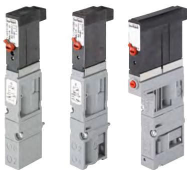
Single valves Type 6524 and Type 6525 designed for REV.1 (FM14 interface) and REV.2 (FM20 interface) cannot be interchanged. Always install REV.2 replacement valves on REV.2 base units.
Burkert Type 8647 accommodates high-response pilot solenoid valves built with flipper armature technology (Type 6144) acting on pneumatic seat valves. These valves deliver switching times of 15 ms to 28 ms with low coil power consumption (0.8 W per coil).
| Valve Type | Circuit Function | Orifice [mm] | Flow Rate QNn [l/min] | Pressure Range [bar] | Opening Time [ms] | Closing Time [ms] | Article No. (REV.2) |
|---|---|---|---|---|---|---|---|
| 6524 | 3/2 NC (CF C) | 4.0 | 300 | 2.5 to 10 | 15 | 28 | 20029918 |
| 6524 | 3/2 NC (Aux Air) | 4.0 | 300 | 1.0 to 10 | 15 | 20 | 20029921 |
| 6524 | 3/2 NC (Vacuum) | 4.0 | 300 | Vac to 7 | 15 | 20 | 20029923 |
| 6524 | 3/2 NO (CF D) | 4.0 | 300 | 2.5 to 10 | 15 | 28 | 20029919 |
| 6525 | 5/2 (CF H) | 4.0 | 300 | 2.5 to 10 | 20 | 28 | 20029920 |
| 6524 | 2× 3/2 NC (CF C) | 4.0 | 300 | 2.5 to 10 | 12 | 20 | 204710 |
| 0460 | 5/3 Closed (CF L) | 2.5 | 200 | 2.0 to 7 | 15 | 20 | 154184 |
| 0460 | 5/3 Exhaust (CF N) | 2.5 | 200 | 2.0 to 7 | 15 | 20 | 154185 |
| 0460 | 5/2 Impulse (CF Z) | 2.5 | 200 | 2.0 to 7 | 15 | 15 | 154183 |
Type 8647 incorporates dedicated hardware architectures to satisfy diverse functional safety and plant trip requirements:
Electronic base modules designated with "EVS" incorporate a pluggable 2-pole screw-type terminal on the top face. Opening this circuit produces an immediate single-pole disconnection of the 24 V DC load supply to all valves connected to that specific base module. The module logic, communication bus, and LC display remain active, reporting "EVS active" to the host controller.
SIA variants of Type 6524 and Type 6525 valves are manufactured without manual overrides and feature an independent secondary wire harness with flying leads. This allows dedicated single-channel safety tripping by an external safety relay, independent of adjacent valves.
For architected safety control conforming to EN ISO 13849-1 and IEC 62061, Type 8647 valve blocks can be positioned downstream of a Siemens F-PM-E 24VDC/8A PPM ST fail-safe power module. When safety shutdown occurs, the F-PM-E disconnects the load supply to the entire potential group, causing all 6524/6525 valves to return to their de-energized rest positions. Compatible REV.2 modules are marked with "FC".
F-PM-E Configuration Parameters
To avoid nuisance tripping during cyclical dark tests, set the following parameters on the Siemens F-PM-E module:
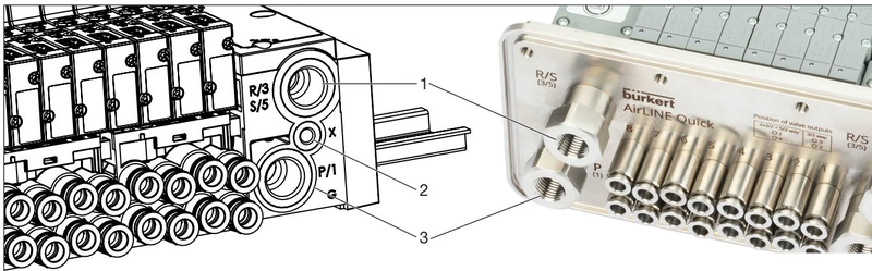
The valve block is delivered fully assembled and mechanically latched. When installing on a 35 mm DIN rail (or ET 200SP HA profile rail), maintain a minimum top clearance of 5 cm to adjacent cable ducts or enclosure walls (8 cm when utilizing EVS pluggable terminals). Tighten the integrated fastening screws clockwise with a torque of approximately 1.8 Nm.
| Connection | Marking | Function | Thread Size | Recommended Torque [Nm] | Max Torque [Nm] |
|---|---|---|---|---|---|
| Connection Unit Port 1 | P / 1 | Compressed air supply | G 1/4 | 4.0 to 7.0 | 20.0 |
| Connection Unit Port 3/5 | R / 3, S / 5 | Common exhaust air | G 1/4 | 4.0 to 7.0 | 20.0 |
| Connection Unit Port X | X | Auxiliary pilot air / Pilot exhaust | M5 | 1.0 to 1.2 | 3.0 |
| Valve Working Ports | 2 (A), 4 (B) | Actuator service lines | D6 push-in | Hand insertion | Hand insertion |
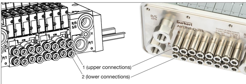
To ensure positive sealing and mechanical retention in D6 push-in fittings:
Type 8647 incorporates multi-tier diagnostics presented via hardware LEDs, an alphanumeric/graphic LC display on each electronic base module, and cyclical fieldbus telegrams:
Thanks to the integrated P shut-off feature in model 20075853, individual valves can be replaced without depressurizing the main air supply manifold:
| Item Description | Quantity / Scope | Article No. |
|---|---|---|
| Replacement Valve Type 6524 3/2-way NC (2.5–10 bar, 24 V DC, REV.2) | 1 piece | 20029918 |
| Replacement Valve Type 6524 3/2-way NO (2.5–10 bar, 24 V DC, REV.2) | 1 piece | 20029919 |
| Replacement Valve Type 6525 5/2-way (2.5–10 bar, 24 V DC, REV.2) | 1 piece | 20029920 |
| Replacement Valve Type 6524 2× 3/2-way NC (2.5–10 bar, 24 V DC, REV.1/2) | 1 piece | 204710 |
| Cover plate for vacant valve position (REV.2, 11 mm station) | 1 piece | 661092 |
| Cover for unused electrical plug-in connection | 1 piece | 653670 |
| Valve seal kit FM20 (for Type 6524 2×3/2-way & REV.2 valves) | 12 seals | 20016305 |
| Valve seal kit FM24 (for Type 6524 3/2-way REV.2 single valves) | 12 seals | 20024336 |
| Module seal kit MP16 (intermediate block gaskets for REV.2) | 4 seals | 20024339 |
| Push-in tube connector D6 mm, nickel-plated brass | 8 pieces | 20024340 |
| Push-in tube connector D6 mm, stainless steel 1.4401 | 8 pieces | 20024341 |
Explore similar products in our catalog


