

PN16

BURKERT 20076176 (Type 8652 AirLINE) is a 16-slot pneumatic valve island with PROFIBUS DPV1, 16x 2x3/2-way CF-C valves, intermediate feed, D10/D6 brass push-in ports, and aluminium AirLINE Quick base.
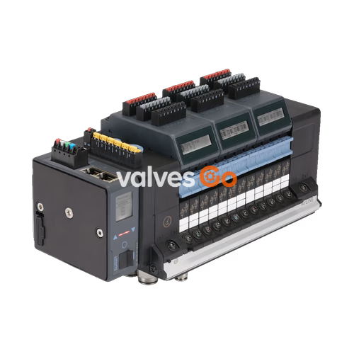
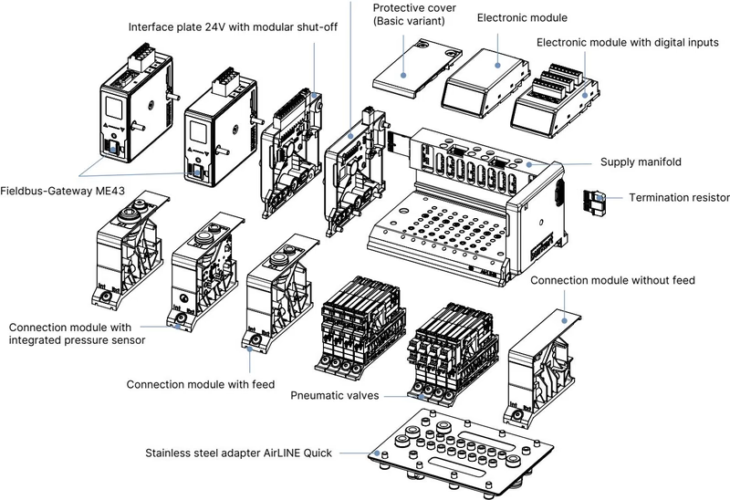
BURKERT 20076176 (Type 8652 AirLINE) is a modular 16-slot pneumatic valve island configured with 16 dual 3/2-way normally closed valves (Circuit function C), integrated PROFIBUS DPV1 fieldbus communication via a 9-pin Sub-D connector, and an aluminium AirLINE Quick adapter plate for direct control cabinet floor mounting. Engineered specifically for process automation environments, each 11 mm wide valve slice operates with a low nominal power consumption of 0.7 W (reducing to 0.175 W after switching) and delivers a nominal flow rate of 310 l/min. The island features internal auxiliary pilot air routing, an integrated intermediate pneumatic feed module, integrated non-return check valves in exhaust ducts 3 (R) and 5 (S), and pneumatic HotSwap in supply port 1 (P).

| Specification Group | Parameter | Value |
|---|---|---|
| Base Identity | Burkert Type | 8652 |
| Base Identity | Article Number (SKU) | 20076176 |
| Valve Configuration | Number of Valve Slots | 16 PCE (11 mm station width) |
| Valve Configuration | Positions 1 through 16 | 2x 3/2-way CF-C (normally closed) |
| Pneumatics | Pressure Range | Vacuum to 10 bar (-1.00 bar to 10.00 bar) |
| Pneumatics | Pilot Pressure Range | 3 bar to 10 bar (internal auxiliary pilot air) |
| Pneumatics | Nominal Flow Rate QNn (Air) | 310 l/min (approx. 3% reduction during HotSwap) |
| Pneumatics | Exhaust Check Valves | Integrated in port 3 (R) and port 5 (S) |
| Pneumatics | HotSwap Capability | Integrated in supply port 1 (P) |
| Pneumatic Ports | Supply Port (1) | Push-in connector D10 mm (nickel-plated brass) |
| Pneumatic Ports | Working Ports (2 and 4) | Push-in connector D6 mm (nickel-plated brass) |
| Pneumatic Ports | Additional Supply Feed | Middle push-in D6/D10 (1 PCE); Left push-in D6/D10; Right without |
| Mechanical | AirLINE Quick Adapter Plate | Anodised aluminium |
| Mechanical | Body / Housing Material | Polyamide (PA) |
| Mechanical | Seal Materials | NBR and PUR |
| Electrical | Operating Voltage | 24 V DC (±10%), residual ripple 1 Vss |
| Electrical | Nominal Power per Valve | 0.7 W (0.175 W after holding power reduction) |
| Electrical | Nominal Current per Valve | 29 mA (10 mA after power reduction) |
| Electrical | Duty Cycle | Continuous operation (100% ED) |
| Electrical | Protection Class | Class III according to DIN EN 61140 / VDE 0140 |
| Communication | Modular Gateway | Type ME43 Fieldbus Gateway |
| Communication | Protocol | PROFIBUS DPV1 |
| Communication | Hardware Interface | Sub-D 9-pin female connector |
| Environmental | Degree of Protection | IP20 naked / IP65 in closed control cabinet with AirLINE Quick |
| Environmental | Ambient Temperature Range | -10 °C to +55 °C |
| Environmental | Medium Temperature Range | -10 °C to +55 °C |
| Environmental | Storage Temperature Range | -20 °C to +60 °C |
| Environmental | Operating Medium | Compressed dry air (lubricated or unlubricated), neutral gases (ISO 8573-1:2010 Class 7.4.4) |
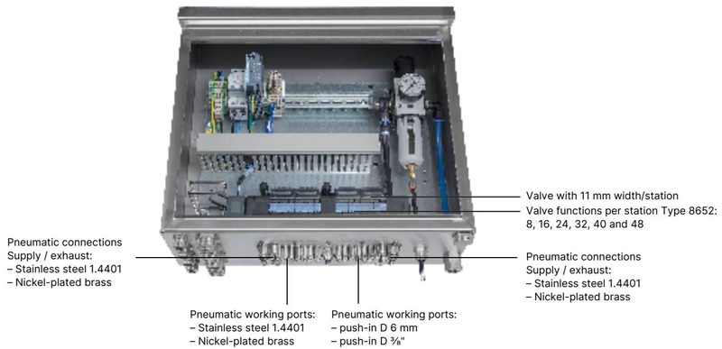
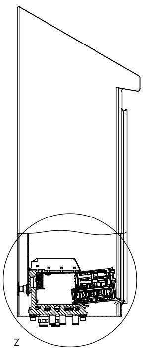
The AirLINE Quick system allows Type 8652 to be mounted directly on the floor or side wall of a control cabinet. All pneumatic working lines (D6 mm) and supply lines (D10 mm) route directly out of the cabinet base through the aluminium adapter plate, eliminating separate bulkhead pass-through fittings and significantly reducing cabinet volume requirements.
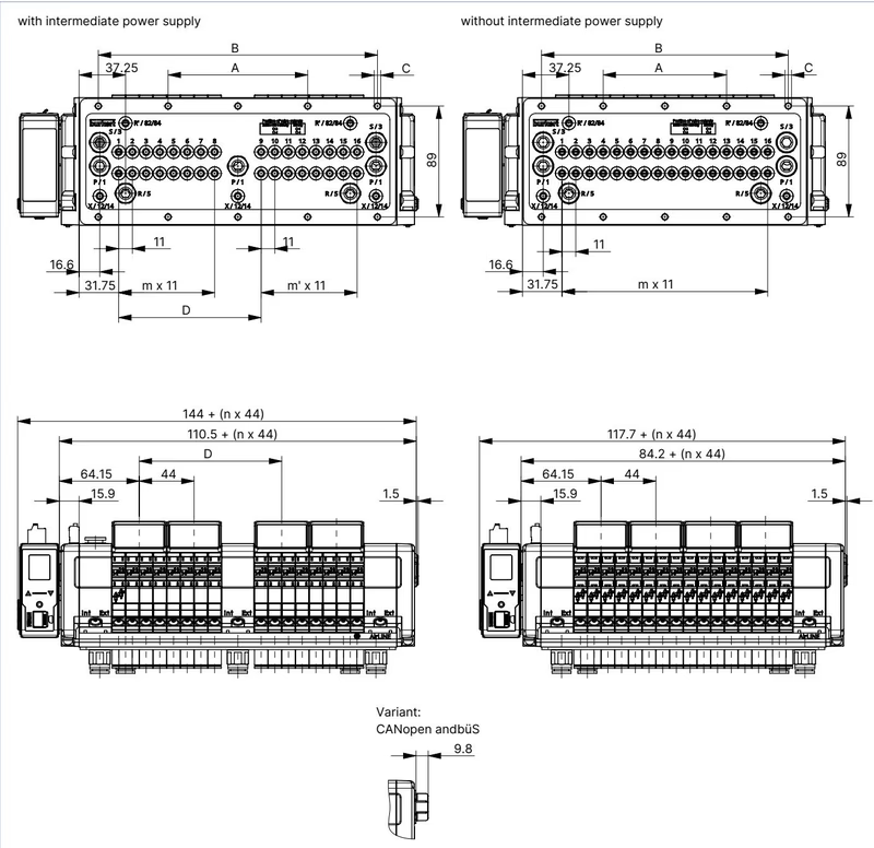
For article 20076176, the valve terminal utilizes the 16-fold configuration with an intermediate supply block. The dimensional parameters defined by Burkert engineering drawings are:
| Variant | A (mm) | B (mm) | C (screws) | D (mm) | m | m' | n |
|---|---|---|---|---|---|---|---|
| 16-fold with intermediate supply (Article 20076176) | 112 | 224 | 10 x M5 | 114.3 | 7 | 7 | 4 |
| 20-fold with intermediate supply | 134 | 268 | 10 x M5 | 158.3 | 11 | 7 | 5 |
| 24-fold with intermediate supply | 156 | 312 | 10 x M5 | 158.3 | 11 | 11 | 6 |
| 16-fold without intermediate supply | 99 | 198 | 10 x M5 | — | 15 | — | 4 |
| 20-fold without intermediate supply | 121 | 242 | 10 x M5 | — | 19 | — | 5 |
| 24-fold without intermediate supply | 143 | 286 | 10 x M5 | — | 23 | — | 6 |
When positioning the valve island inside the enclosure, ensure sufficient clearance between the front edge of the valve island and the cabinet door/front framework to enable unhindered removal and insertion of valve slices during live pneumatic HotSwap.
The 24 V interface plate separates valve coil actuation power from the logic and communication module power, ensuring that a safety cutoff or disruption on the actuator supply does not interrupt communication with the supervisory PLC.
| Terminal Block | Terminal Pin | Conductor Colour Code | Signal Assignment |
|---|---|---|---|
| Communication & Logic (5-pin spring-loaded) | Pin 1 | Red | 24 V DC (Logic) |
| Communication & Logic (5-pin spring-loaded) | Pin 2 | White | CAN_H (büS interface) |
| Communication & Logic (5-pin spring-loaded) | Pin 3 | Green | Shielding |
| Communication & Logic (5-pin spring-loaded) | Pin 4 | Blue | CAN_L (büS interface) |
| Communication & Logic (5-pin spring-loaded) | Pin 5 | Black | 0 V DC (GND) |
| Pneumatic Valves (2-pin spring-loaded) | Pin 1 | Red | AUX 24 V DC (Valve coil supply) |
| Pneumatic Valves (2-pin spring-loaded) | Pin 2 | Black | 0 V DC (Valve GND) |
Terminal Requirements
Both spring-loaded blocks accommodate conductor cross-sections up to 1.5 mm².
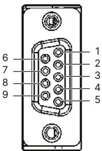
| Pin | Signal | Description |
|---|---|---|
| 1 | Shielding | Cable shield connection |
| 2 | M24 | Optional ground reference |
| 3 | RxD/TxD-P | Receive / Transmit data positive (B-line) |
| 4 | CNTR-P | Control signal P (optional) |
| 5 | DGND | Data ground |
| 6 | +5 V | Terminating resistor supply voltage |
| 7 | +24 V | Optional 24 V auxiliary voltage |
| 8 | RxD/TxD-N | Receive / Transmit data negative (A-line) |
| 9 | CNTR-N | Control signal N (optional) |
Article 20076176 is fully populated with 16 dual 3/2-way normally closed valve slices (Circuit Function C). Each slot contains two pilot-controlled solenoid valves utilizing Type 6164 pilot operators. Manual overrides are incorporated on each valve position.
| Circuit Function | Description | Nominal Diameter (mm) | QNn Air (l/min) | Pressure Range (bar) | Opening Time (ms) | Closing Time (ms) | Operating Voltage | Spare Valve Article No. (incl. screws) |
|---|---|---|---|---|---|---|---|---|
| CF C | 2x 3/2-way NC, servo-assisted, with manual override | 4 | 270 | Vac...10 (pilot 3...10) | 15 | 15 | 24 V DC | 301374 (REF 296031) |
| CF C | 1x 3/2-way NC, servo-assisted, with manual override | 4 | 270 | Vac...10 (pilot 3...10) | 15 | 15 | 24 V DC | 20102334 (REF 20088974) |
| CF D | 2x 3/2-way NO, servo-assisted, with manual override | 4 | 310 | Vac...10 (pilot 3...10) | 15 | 15 | 24 V DC | 301375 (REF 296032) |
| CF H | 5/2-way, servo-assisted, with manual override | 4 | 290 | Vac...10 (pilot 3...10) | 20 | 25 | 24 V DC | 301376 (REF 296033) |
| CF Z | 5/2-way impulse, 2 coils, with manual override | 4 | 290 | Vac...10 (pilot 3...10) | 20 | 25 | 24 V DC | 301377 (REF 296034) |
| CF L | 5/3-way, middle position closed, with manual override | 4 | 275 | Vac...10 (pilot 3...10) | 15 | 15 | 24 V DC | 301380 (REF 296036) |
| CF M | 5/3-way, middle position pressurized, with manual override | 4 | 300 | Vac...10 (pilot 3...10) | 20 | 20 | 24 V DC | 301379 (REF 296035) |
| CF N | 5/3-way, middle position exhausted, with manual override | 4 | 300 | Vac...10 (pilot 3...10) | 20 | 20 | 24 V DC | 301381 (REF 296039) |
| Dummy | Blanking slice for unused valve slot | — | — | — | — | — | — | 335779 (REF 327614) |
Integrated non-return check valves located directly in the common exhaust ducts prevent cross-exhaust backpressure spikes from entering de-energized actuators. This prevents inadvertent process actuator movements when neighbouring high-volume valves vent simultaneously.
The integrated pneumatic HotSwap shut-off valve enables online replacement of individual valve slices while the manifold remains pressurized up to 10 bar. Nominal airflow rate QNn decreases by approximately 3% due to the internal check mechanism.
Hazardous Area Operational Restrictions
According to ATEX/IECEx supplementary directives (BVS 20 ATEX E 031 U / IECEx BVS 20.0024 U):
| Category | Description | Article Number |
|---|---|---|
| Replacement Valve | Dual 3/2-way NC (CF C) replacement valve with screws | 301374 |
| Gateway Spare | Fieldbus gateway Type ME43 (PROFIBUS DP) | 301803 |
| Connector Plugs | 5-pin spring-loaded terminal for communication and logic power | 920180 |
| Connector Plugs | 2-pin spring-loaded terminal for pneumatic valve power supply | 920442 |
| AirLINE Quick Hardware | M5x10 A2 DIN 6912 cabinet fastening screw set (pack of 10) | 308661 |
| AirLINE Quick Hardware | Height adapter for 16-fold base with intermediate feed | 754962 |
| AirLINE Quick Hardware | Retaining plate for control cabinet exterior (16-fold with intermediate feed) | 60005568 |
| AirLINE Quick Hardware | Blind cover plate for 16-fold base with intermediate feed | 754967 |
| Software Tool | Bürkert Communicator Type 8920 commissioning software | Type 8920 |
| Hardware Kit | USB büS interface set 1 (Type 8923) with terminating resistor and power supply | 772426 |
Explore similar products in our catalog


