


Up to 99.8% Efficiency

BURKERT 20079579 (Type 3361) is an electromotive 2-way globe control valve with DN 15 flanged port, AG2 1300 N actuator, 8 mm seat, 2.1 m³/h Kvs, 24 V DC supply, PROFINET and büS communication, and SAFEPOS energy-pack.
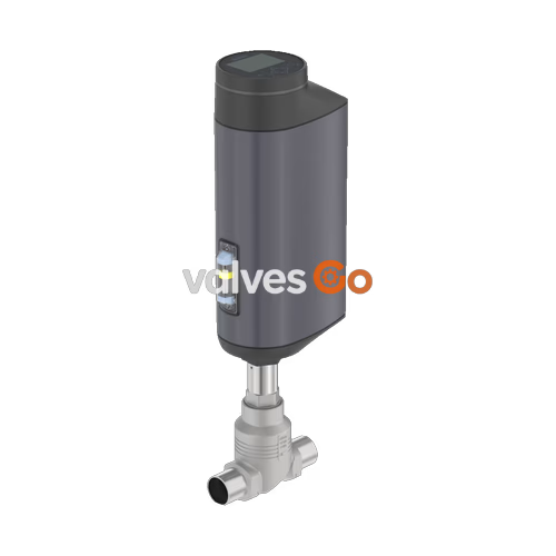
BURKERT 20079579 (Type 3361) is an electromotive 2-way globe control valve engineered for demanding process automation tasks. The valve assembly pairs an AG2 linear actuator delivering 1300 N nominal positioning force with a stainless steel CF3M globe valve body. The process port is configured as a DN 15 flanged connection conforming to DIN EN 1092-1 PN 25, with a face-to-face dimension of 130 mm per DIN EN 558-1 FTF 1. The drive system utilizes a brushless DC motor and precision ball screw mechanism that shifts the control cone at 6 mm/s, achieving a typical closing time of 3.4 s and a position control dead band of ±0.1%. Fluid flows against the closing direction (flow below seat, 2 → 1) past an 8 mm exchangeable valve seat, providing an equal-percentage flow characteristic with a 50:1 theoretical rangeability, a rated Kvs of 2.1 m³/h (Cv 2.4 gal/min), and Class IV seat leakage according to DIN EN 60534-4.
The valve operates on a 24 V DC power supply and features integrated digital position control, an optical 360° LED status ring, a local display module with operating keys, and a PROFINET industrial Ethernet gateway with an integrated 2-port switch alongside the büS service interface. In the event of an external power loss, an integrated SAFEPOS energy-pack emergency power storage automatically drives the valve to the pre-configured normally closed safety position. The closed exterior housing design complies with IP65/IP67 ingress ratings (NEMA 4X) and holds Ecolab detergent cleaning certification, making the unit suitable for hygienic and chemically demanding wash-down environments.
| Technical Parameter | Specification / Value |
|---|---|
| Valve Type | Type 3361 electromotive 2-way globe control valve |
| Order Identifier (Ident) | 20079579 |
| Nominal Diameter (Port Size) | DN 15 (NPS 1/2") |
| Port Connection Type | Flange DIN EN 1092-1 PN 25 (face-to-face 130 mm acc. to DIN EN 558-1) |
| Valve Seat Diameter | 8 mm (5/16") |
| Flow Coefficient Kvs (Water) | 2.1 m³/h (Cv: 2.4 gal/min) |
| Flow Characteristic | Equal percentage 50:1 (acc. to DIN EN 60534-2-4) |
| Flow Direction | Below seat (flow direction 2 → 1) |
| Operating Pressure Range | 0 to 25 bar(g) |
| Nominal Pressure Rating | PN 25 (DIN EN 1333) / Class 150 (DIN EN 1759) |
| Seat Leakage Class | Class IV (DIN EN 60534-4) |
| Actuator Size and Nominal Force | AG2 (1300 N) |
| Travel Speed | 6 mm/s |
| Typical Closing Time | 3.4 s (3400 ms) |
| Position Control Dead Band | ±0.1% |
| Safety Position on Power Failure | Normally closed (delivery status), powered by SAFEPOS energy-pack |
| Operating Voltage | 24 V DC ± 10% (maximum residual ripple 10%) |
| Operating Current | Max. 3 A (at max. load, including 1 A SAFEPOS charging); +2 A at min. temp. |
| Standby Power Consumption | 2 to 5 W |
| Electrical Protection Class | Class III (DIN EN 61140) |
| Operating Duty Cycle | 100% continuous |
| Communication Protocols | büS (CAN-based) + PROFINET (integrated fieldbus gateway) |
| Local User Interface | Display module with operation keys, büS service port, 360° LED ring |
| Medium Temperature Range | -10 °C to +230 °C |
| Ambient Temperature Range | -25 °C to +65 °C (without modules; subject to derating) |
| Fluid Viscosity Limit | Up to 600 mm²/s |
| Permissible Process Media | Steam, neutral gases, water, alcohols, oils, fuels, hydraulic fluids, salt solutions, organic solvents |
| Degree of Protection | IP65/IP67 (DIN EN 60529), NEMA 4X |
| Installation Position | Any orientation; actuator upright orientation recommended |
| Actuator Weight | Approx. 5.5 kg (AG2 actuator alone; total valve weight depends on body) |
BURKERT 20079579 complies with applicable European harmonized standards and international hygiene specifications:
Auxiliary Certifications in Series Documentation
The Type 3361 product family includes options for ATEX/IECEx Zone 2/22 (Code PX48), cULus listing (Code PU11: UL 61010-1 and CAN/CSA-C22.2 No. 61010-1), UBA drinking water compliance up to +85 °C (Code PF39), Chinese GB food standards (Code PL10), TA-Luft air quality sealing (Code PM01), and certified oxygen/hydrogen variants. Article 20079579 carries standard IP65/IP67, FDA, EC 1935/2004, and Ecolab conformity.
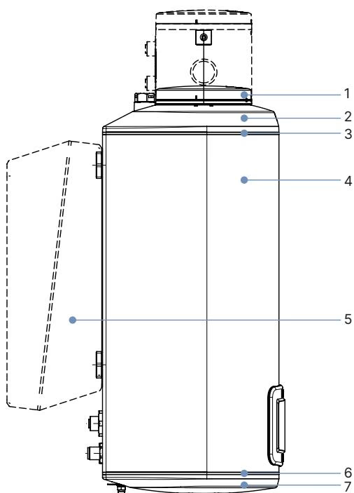
| Item | Actuator Component | Material |
|---|---|---|
| 1 | Display housing / blind cover / gateway housing | PPS (standard) |
| 2 | Actuator cover | PPS |
| 3 | Seal rings | EPDM |
| 4 | Actuator housing | Powder-coated die-cast aluminium |
| 6 | Seals | EPDM |
| 7 | Actuator base | PPS |
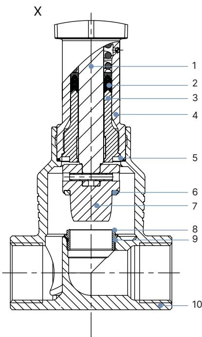
| Item | Valve Component | Material Specification |
|---|---|---|
| 1 | Spindle | Stainless steel 1.4401 (316) / 1.4404 (316L) |
| 2 | Spindle seal | PTFE V-seals (filled) with spring compensation |
| 3 | Spindle guide | Stainless steel 1.4404 (316L) |
| 4 | Packing gland tube | Stainless steel 1.4401 (316) |
| 5 | Valve body seal | Graphite or PTFE |
| 6 | Seat seal | Stainless steel 1.4571 (metal-to-metal sealing) |
| 7 | Control cone | Stainless steel 1.4571 |
| 8 | Valve seat | Stainless steel 1.4571 (screwed-in, exchangeable) |
| 9 | O-ring valve seat | EPDM or PTFE |
| 10 | Valve body | Cast stainless steel CF3M |
Chemical Compatibility Verification
Material resistance for specific aggressive media can be verified using the Bürkert resistApp chemical resistance tool at www.burkert.com.
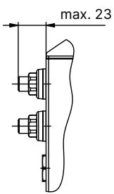
| Nominal Diameter DN | Nominal Diameter NPS | H1 Standard Height (mm) | H2 Fieldbus Gateway Height (mm) |
|---|---|---|---|
| 10 | 3/8" | 417 | 489 |
| 15 | 1/2" | 417 | 489 |
| 20 | 3/4" | 423 | 495 |
| 25 | 1" | 446 | 518 |
| 32 | 1 1/4" | 474 | 546 |
| 40 | 1 1/2" | 479 | 551 |
| 50 | 2" | 485 | 557 |
Note on height dimensions: In the closed position without sealing function, the actuator is raised by approximately 2 mm. Article 20079579 includes the fieldbus gateway module, corresponding to height H2 = 489 mm.
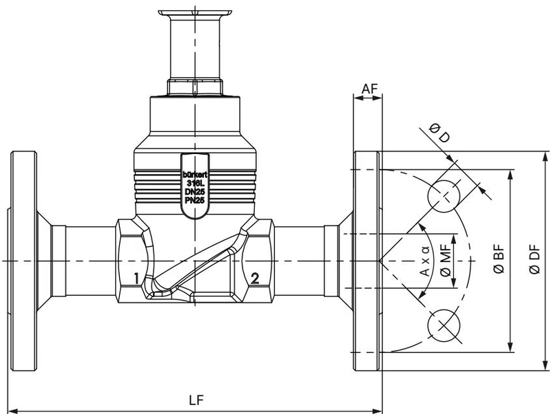
| DN | ∅ DF (Flange OD) | LF (Face-to-Face FTF 1) | ∅ BF (Bolt Circle) | AF (Flange Thickness) | ∅ D (Hole Dia.) | A × α (Bolt Pattern) | ∅ MF (Port Bore ID) |
|---|---|---|---|---|---|---|---|
| 10 | 90 mm | 130 mm | 60 mm | 16 mm | 14 mm | 4 × 90° | 13.6 mm |
| 15 | 95 mm | 130 mm | 65 mm | 16 mm | 14 mm | 4 × 90° | 18.1 mm |
| 20 | 105 mm | 150 mm | 75 mm | 18 mm | 14 mm | 4 × 90° | 23.7 mm |
| 25 | 115 mm | 160 mm | 85 mm | 18 mm | 14 mm | 4 × 90° | 29.7 mm |
| 32 | 140 mm | 180 mm | 100 mm | 18 mm | 18 mm | 4 × 90° | 38.4 mm |
| 40 | 150 mm | 200 mm | 110 mm | 18 mm | 18 mm | 4 × 90° | 44.3 mm |
| 50 | 165 mm | 230 mm | 125 mm | 20 mm | 18 mm | 4 × 90° | 56.3 mm |
| 65 | 185 mm | 290 mm | 145 mm | 22 mm | 18 mm | 8 × 45° | 66.0 mm |
| 80 | 200 mm | 310 mm | 160 mm | 24 mm | 18 mm | 8 × 45° | 81.0 mm |
| 100 | 235 mm | 350 mm | 190 mm | 24 mm | 22 mm | 8 × 45° | 100.0 mm |
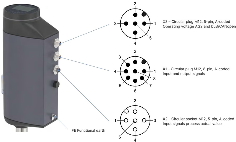
Article 20079579 utilizes M12 industrial circular connectors for electrical supply, digital/analogue signals, and industrial Ethernet fieldbus connection.
| Connector Identifier | Connector Design | Function in Article 20079579 |
|---|---|---|
| X1 | M12 circular plug, 8-pin, A-coded | Digital and analogue input/output signals (standard) |
| X2 | M12 circular socket, 5-pin, A-coded | Process actual value input (used only on process controller models) |
| X3 | M12 circular plug, 5-pin, A-coded | 24 V DC supply voltage and büS / CANopen interface |
| X7 | 2 × M12 circular socket, 4-pin, D-coded | PROFINET industrial Ethernet fieldbus (2-port switch) |
| Pin Number | Signal Assignment |
|---|---|
| 1 | Digital input + |
| 2 | GND for digital input and digital outputs |
| 3 | Digital output 2 + |
| 4 | Digital output 1 + |
| 5 | Analogue output - |
| 6 | Analogue output + |
| 7 | Set-point value / Analogue input - |
| 8 | Set-point value / Analogue input + |
| Pin Number | Signal Assignment |
|---|---|
| 1 | CAN shield / cable shield |
| 2 | Operating voltage 24 V DC ± 10% |
| 3 | GND / CAN_GND |
| 4 | CAN_H |
| 5 | CAN_L |
| Pin Number | Signal Assignment |
|---|---|
| 1 | Transmit Data + (TD+) |
| 2 | Receive Data + (RD+) |
| 3 | Transmit Data - (TD-) |
| 4 | Receive Data - (RD-) |
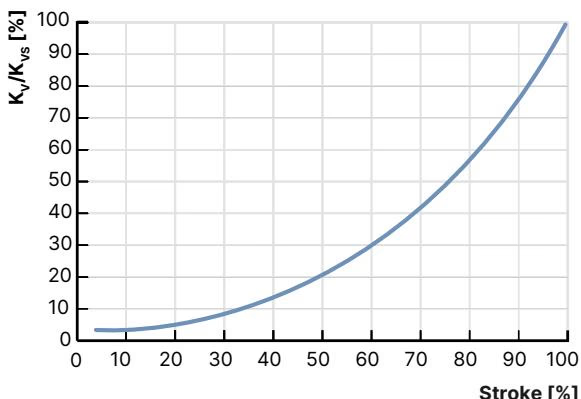
Type 3361 features an equal-percentage flow characteristic curve in accordance with DIN EN 60534-2-4. Flow is routed under the valve seat (flow direction 2 → 1) to eliminate water hammer and maintain continuous control stability.
| Seat Size (mm) | Actuator Force (N) | Max. Differential Pressure [bar(g)] | Theoretical Rangeability | Kv at 10% Stroke (m³/h) | Kv at 20% Stroke (m³/h) | Kv at 30% Stroke (m³/h) | Kv at 40% Stroke (m³/h) | Kv at 50% Stroke (m³/h) | Kv at 60% Stroke (m³/h) | Kv at 70% Stroke (m³/h) | Kv at 80% Stroke (m³/h) | Kv at 90% Stroke (m³/h) | Kvs at 100% Stroke (m³/h) |
|---|---|---|---|---|---|---|---|---|---|---|---|---|---|
| 3 | 1300 | 25 (IV) | 20:1 | 0.005 | 0.009 | 0.013 | 0.019 | 0.026 | 0.034 | 0.044 | 0.060 | 0.077 | 0.1 |
| 3 | 1300 | 25 (IV) | 20:1 | 0.009 | 0.015 | 0.023 | 0.033 | 0.046 | 0.063 | 0.085 | 0.11 | 0.16 | 0.2 |
| 4 | 1300 | 25 (IV) | 30:1 | 0.023 | 0.033 | 0.049 | 0.070 | 0.097 | 0.14 | 0.18 | 0.26 | 0.35 | 0.5 |
| 6 | 1300 | 25 (IV) | 50:1 | 0.007 | 0.011 | 0.045 | 0.085 | 0.16 | 0.26 | 0.41 | 0.65 | 1.1 | 1.25 |
| 8 | 1300 | 25 (IV) | 50:1 | 0.080 | 0.11 | 0.13 | 0.19 | 0.27 | 0.43 | 0.63 | 0.95 | 1.6 | 2.1 |
| 10 | 1300 | 25 (IV) | 50:1 | 0.11 | 0.15 | 0.19 | 0.31 | 0.49 | 0.75 | 1.1 | 1.7 | 2.5 | 3.1 |
| 15 | 1300 | 25 (IV) | 50:1 | 0.17 | 0.22 | 0.35 | 0.52 | 0.80 | 1.2 | 1.8 | 2.7 | 3.7 | 4.3 |
Article 20079579 features seat size 8 mm with stainless steel metallic seating, yielding Kvs = 2.1 m³/h and Class IV seat leakage up to 25 bar(g).
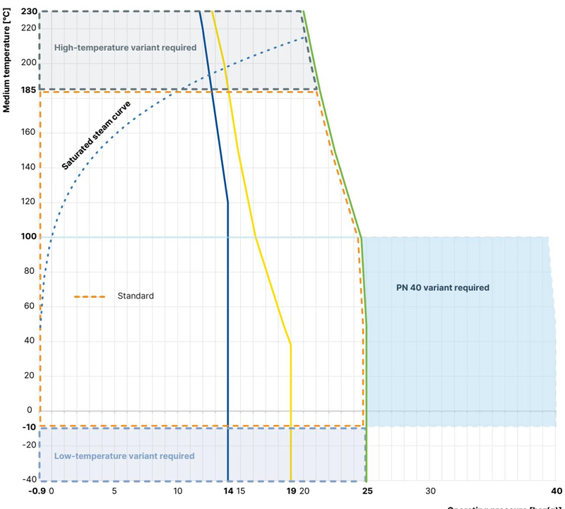
Process pressure is limited by both maximum actuator operating pressure and standard pressure-temperature ratings. Under DIN EN 12516-1 PN 25, the pressure envelope is bounded by the saturated steam curve for water up to the maximum medium temperature of +230 °C.
| Tight Sealing Required | Seat Seal Material | Leakage Class (DIN EN 60534-4) | Permissible Medium Temperature | Application Note |
|---|---|---|---|---|
| No (additional shut-off valve recommended) | Stainless steel 1.4571 | Class III / IV | -40 °C to +230 °C | Impervious to harsh thermal/mechanical conditions; hardened trim available for cavitation or abrasive media. (Supplied with 20079579) |
| Yes (soft sealing) | PTFE | Class VI | -40 °C to +130 °C (recommended ≤ +130 °C) | Provides bubble-tight shut-off without upstream isolation valve. |
| Yes (soft sealing) | PEEK | Class VI | -10 °C to +230 °C (recommended > +130 °C) | High-temperature polymer soft seal for tight shut-off up to +230 °C. |
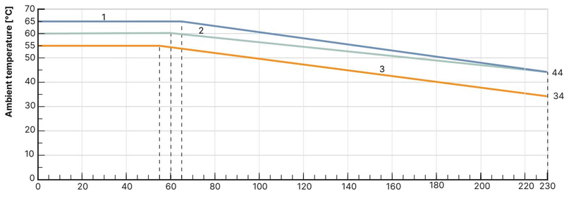
The permissible ambient temperature depends directly on the process fluid temperature. For Article 20079579, which combines the AG2 actuator with the SAFEPOS energy-pack and fieldbus gateway module, Curve 3 applies:
At maximum fluid temperatures up to +230 °C, the permissible ambient temperature must be derated according to Curve 3 to prevent thermal overload of the actuator electronics.
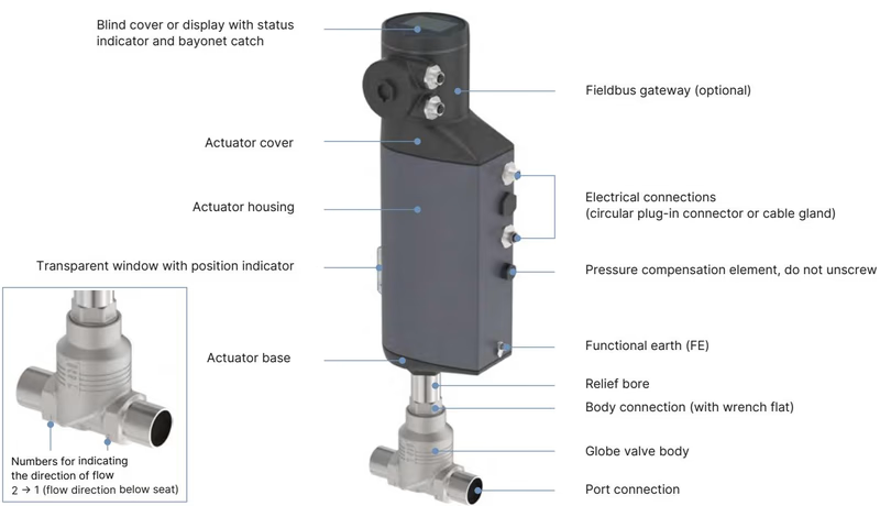
The AG2 actuator incorporates an electronically commutated brushless DC motor coupled to a reduction gear and a precision recirculating ball screw spindle system. This mechanical arrangement converts rotational motion into linear thrust with zero backlash, holding the control cone securely in position even under maximum media line pressure without consuming continuous holding current.
Article 20079579 includes the integrated SAFEPOS energy-pack module:
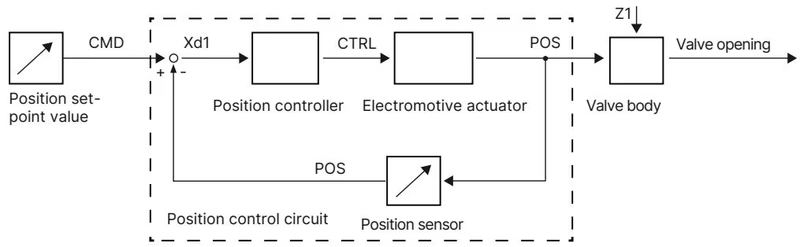
The integrated positioner compares the target position value (CMD) received via PROFINET or analogue input with the actual position value (POS) measured by an internal contact-free displacement sensor. When a control deviation (Xd1) exists, the microprocessor modulates the motor drive (CTRL) to adjust the spindle position until deviation falls within the ±0.1% dead band.
Diagnostic algorithms continually track stem travel cycles, operating hours, temperature profiles, and packing gland integrity, issuing preventive maintenance notifications before field failure occurs.
High Pressure and Electrical Shock Hazard
Before dismantling the valve from the piping system or opening the actuator housing, depressurize and vent all process lines, drain residual medium, switch off the 24 V DC supply, and completely discharge the SAFEPOS energy-pack. Wait until the 360° LED ring is entirely extinguished.
| Assembly Point / Threaded Joint | Tool Size / Thread | Specified Tightening Torque |
|---|---|---|
| Body Connection (DN 10/15) | Open-end wrench on body connection | 45 ± 3 Nm (33 ± 2 lbf ft) |
| Body Connection (DN 20) | Open-end wrench on body connection | 50 ± 3 Nm (37 ± 2 lbf ft) |
| Body Connection (DN 25) | Open-end wrench on body connection | 60 ± 3 Nm (44 ± 2 lbf ft) |
| Valve Seat Installation (Seat Size 3–15, DN 10/15) | Installation tool 652604 | 20 + 3 Nm |
| Valve Seat Installation (Seat Size 20, DN 20) | Installation tool 652605 | 28 + 3 Nm |
| Valve Seat Installation (Seat Size 25, DN 25) | Installation tool 652606 | 40 + 5 Nm |
| Lower Spindle Guide (ø10 mm Spindle, DN 10/15) | Modified socket wrench 683220 (SW19) | 15 Nm |
| Lower Spindle Guide (ø10 mm Spindle, DN 20) | Modified socket wrench 683222 (SW21) | 25 Nm |
| Actuator Base Screws (4× screws to housing) | Hex socket head | 5 Nm (tighten crosswise) |
| Actuator Cover Fastening Screws (4× screws) | Hexalobular internal T25 | 5 Nm (tighten crosswise) |
| Fieldbus Gateway Fastening Screw | Hex socket head 3 mm | 1.1 Nm |
| SAFEPOS Energy-Pack Locking Screw | Hexalobular internal T10 | 1.1 Nm |
| Mechanical Manual Override | Hex key 3 mm | Max. 2 Nm (do not exceed) |
Critical Disassembly Requirement
To prevent permanent mechanical damage to the valve body seat and the control cone contour, the valve must be positioned at least 1/3 open before unscrewing the actuator from the valve body.
After replacing the valve seat, control cone, spindle seal packing, or after reinstalling the actuator onto the valve body, the automatic X.TUNE function must be executed to calibrate the position control system to the mechanical stroke limits:
| Accessory Description | Article Identifier |
|---|---|
| SAFEPOS energy-pack replacement module (for AG2 actuator) | 285834 |
| Control cone replacement set (Type 3361, DN 10/15, Seat Size 8, Steel/steel) | 149 935 |
| Valve seat replacement set (Type 3361, DN 10/15, Seat Size 8, with graphite seal) | 262 147 |
| Packing gland seal kit (ø10 mm spindle, DN 15/20) | 285 685 |
| Stainless steel spindle guide for packing gland (DN 15 body, ø10 mm spindle) | 246 577 |
| Valve seat installation tool (for Type 3361, DN 15 body) | 652 604 |
| Modified socket wrench for packing gland (SW19, ø10 mm spindle, DN 15) | 683 220 |
| Parameter transfer SIM card | 291 773 |
| Holding device for line connection clamping (DN 15 to DN 20) | 693 770 |
| M12 circular socket with 5 m cable, 4-pin, A-coded (for X3 power AG2) | 918 038 |
| M12 circular socket with 2 m cable, 8-pin, A-coded (for X1 I/O signals) | 919 061 |
| M12 circular plug to straight M12 plug cable, 4-pin, D-coded, 5 m (for X7 PROFINET) | 775 043 |
| M12 circular plug to RJ45 plug cable, 4-pin, D-coded, 5 m (for X7 PROFINET) | 775 053 |
| USB-büS interface set 1 (Type 8923 with power supply, stick, terminating resistor, Y-splitter) | 772 426 |
| USB-büS interface set 2 (Type 8923 stick, terminating resistor, Y-splitter) | 772 551 |
| büS adapter cable (M12 to micro USB büS service interface, length 0.3 m) | 774 931 |
| Bürkert Communicator configuration software | Type 8920 |
Explore similar products in our catalog


