Type 2032

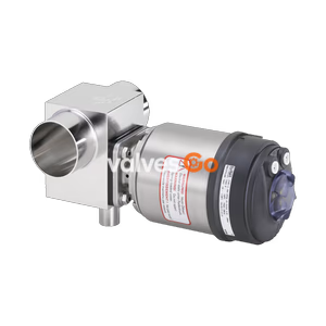
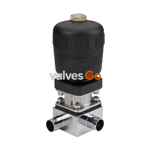
Burkert 20084885 Type 2104 is a pneumatic stainless steel T-diaphragm valve with ASME BPE DN 50 weld ends, PTFE/EPDM diaphragm, NC function, and operating pressures up to 10 bar.
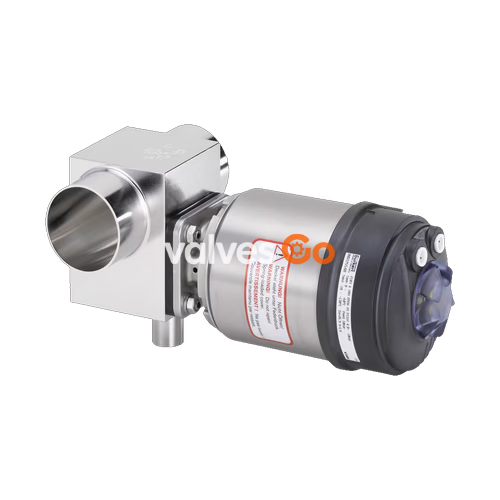
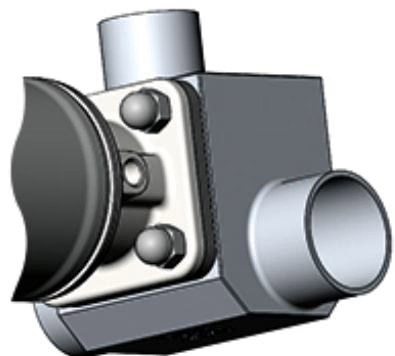
BURKERT 20084885 (Type 2104) is a pneumatically operated 3/2-way T-diaphragm valve designed for decentralized hygienic automation. The valve assembly integrates a stainless-steel-encased ELEMENT piston actuator, a zero-deadleg T-valve body machined from 1.4435 / 316L block material, and a PTFE/EPDM dual-layer diaphragm. Operating under Control Function A (normally closed by spring force), the valve controls ultra-pure, sterile, aggressive, or abrasive fluids at medium operating pressures from 0 bar to 10 bar. Process connections are weld ends engineered to ASME BPE and DIN 11866 Series C standards at DN 50 (outer diameter 50.8 mm / 2 inch with 1.65 mm wall thickness).
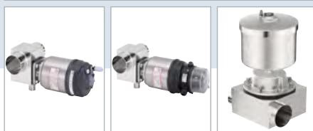
The Type 2104 architecture features internal pilot air routing to eliminate ambient air intake into the spring chamber. With an IP65/IP67 and NEMA 4X enclosure rating, the assembly withstands direct external washdown protocols and CIP/SIP inline steam sterilisation cycles. The fluid contact zone meets pharmaceutical standards, including FDA 21 CFR 177.1550/177.2600, USP Class VI compliance, and EC Regulation 1935/2004.
| Attribute | Source Specification |
|---|---|
| Article Number | 20084885 |
| Type Family | Type 2104 ELEMENT |
| Construction | Complete valve assembly |
| Control Function | A (Normally closed, NC by spring force) |
| Fluidic Ports | 3 ports, 2 switching positions (3/2-way T-valve) |
| Port 1 Connection Type | Weld end |
| Port 1 Pipe Standard | ASME BPE / DIN 11866 Series C |
| Nominal Diameter | DN 50 (2 inch) |
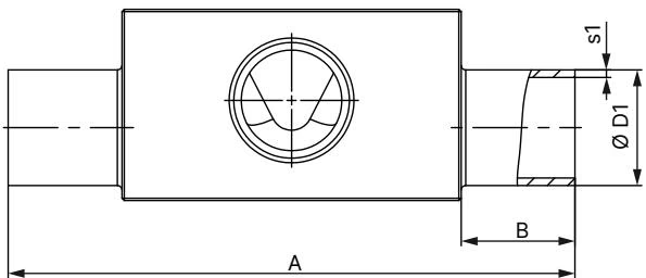
| Pipe Dimensions | Outer diameter 50.8 mm (2.000 in), wall thickness 1.65 mm (0.065 in), inner diameter 47.5 mm |
| Valve Body Material | Stainless steel block material 1.4435 / 316L |
| Diaphragm Material | PTFE with EPDM backing membrane (code EA) |
| Actuator Size | 130 mm diameter (Code P) |
| Actuator Envelope | Stainless steel 1.4561 (316Ti) |
| Actuator Internal Body | Polyphenylene sulphide (PPS) |
| Nominal Pressure Range | 0 bar to 10 bar (PN 16 / Class 150) |
| Pilot Pressure Range | 5.5 bar to 7.0 bar |
| Medium Temperature | -10 °C to +130 °C (Steam sterilisation max. +140 °C for 60 min) |
| Ambient Temperature | -10 °C to +55 °C |
| Pilot Air Interface | ELEMENT interface, push-in connector for 6 mm tubing |
| Cleaning Capabilities | Full CIP (Clean-in-Place) and SIP (Sterilise-in-Place) capability |
| Manual Override | None |
| Position Indicator | Without electrical indicator (optical cap standard) |
| Documentation Enclosed | Manufacturer test certificate 3.1, Diaphragm declaration 2.1 |
The ELEMENT drive housing combines a PPS core with an external 1.4561 (316Ti) stainless steel protective casing. This construction shields internal mechanical and pneumatic components from corrosive cleanroom detergents, atmospheric chemicals, and thermal shock.
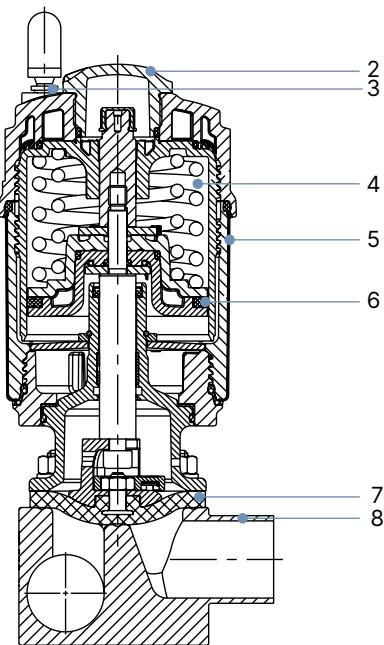
| Item No. | Component | Material |
|---|---|---|
| 1 | Ground terminal | Stainless steel 1.4301 / 1.4305 (included on ATEX/IECEx variants) |
| 2 | Optical position cap | Polysulfone (PSU) |
| 3 | Pilot air ports | PP push-in connector standard (6 mm / 1/4 in); optional G 1/8 stainless steel 1.4305 |
| 4 | Actuator body | Polyphenylene sulphide (PPS) |
| 5 | Actuator cover | Stainless steel 1.4561 (316Ti) |
| 6 | Piston seal | Fluorocarbon elastomer (FKM) |
| 7 | Diaphragm | PTFE/EPDM dual-layer (EA), EPDM (AD), Advanced PTFE (EU), GYLON laminate (ER) |
| 8 | Valve body | Stainless steel block material 1.4435 (DIN EN 10088) / 316L (ASTM A479 / ASME BPE) |
Wetted interior body surfaces are finished to controlled hygienic criteria: mechanically polished to Ra ≤ 0.5 µm (ASME BPE SF1) or electropolished to Ra ≤ 0.38 µm (ASME BPE SF4 / DIN HE4). External surfaces maintain Ra ≤ 1.6 µm.
Under Control Function A, closing force is produced by an internal spring pack that drives the compressor and pushes the diaphragm against the internal weir. For diaphragm size 50 mounted to a 130 mm (P) actuator, the pilot pressure requirements and media sealing capabilities are strictly defined:
Operating Pressure and Thermal Limits
Do not use the diaphragm as a permanent steam shut-off valve. Steam sterilisation is rated to a maximum of +140 °C for up to 60 minutes with the PTFE/EPDM diaphragm. Prolonged exposure beyond recommended time and temperature thresholds accelerates elastomer degradation and necessitates reduced inspection intervals.
Type 2104 T-bodies machined from block material integrate the main run and branch into a single piece to prevent dead legs and flow stagnation.
SODI-SODI)The pneumatic actuator interface can be rotated 360° relative to the body to permit unobstructed positioning of pilot air lines and electrical conduits. The valve can be combined directly with decentralised automation heads:
Avoid Thermal Damage During Welding
Do not weld the valve body into the pipeline while the actuator and diaphragm are mounted. Heat conducted through the stainless steel block will destroy the diaphragm and warp the actuator guides. Always unbolt and remove the actuator and diaphragm prior to welding.

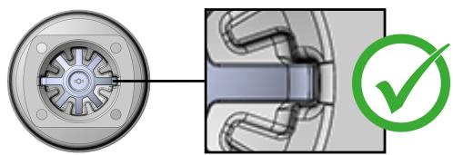
When reinstalling the actuator on the valve body for Control Function A:
| Diaphragm Size | EPDM / FKM Diaphragms | PTFE / Advanced PTFE / GYLON® Diaphragms |
|---|---|---|
| 8 | 2.0 Nm | 2.5 Nm |
| 15 | 3.5 Nm | 4.0 Nm |
| 20 | 4.0 Nm | 4.5 Nm |
| 25 | 5.0 Nm | 6.0 Nm |
| 40 | 8.0 Nm | 10.0 Nm |
| 50 (Article 20084885) | 12.0 Nm | 15.0 Nm |
| 65 | 20.0 Nm | 30.0 Nm |
| 80 | 30.0 Nm | 40.0 Nm |
| 100 | 40.0 Nm | 50.0 Nm |
Diaphragms are subject to mechanical flexure and thermal wear. After the initial inline steam sterilisation cycle, check and retighten the body screws crosswise to compensate for elastomer settling. Conduct visual inspections at the relief bore regularly; any fluid emergence indicates diaphragm leakage and mandates immediate replacement.
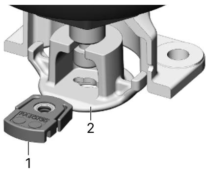
Converting Between Diaphragm Materials
When switching from a PTFE diaphragm (bayonet) to an EPDM diaphragm (threaded) on size 50, place the threaded insert into the compressor pocket before screwing in the EPDM diaphragm hand-tight, then back off 1/2 turn anticlockwise. When switching back from EPDM to PTFE, remove the threaded insert completely. Leaving the insert installed with a bayonet diaphragm will crush the diaphragm and cause severe valve damage.
Store spare diaphragms in compliance with DIN 7716 and ISO 2230 standards between +5 °C and +25 °C in dry (<65% relative humidity), UV-shielded, airtight containers away from ozone-generating equipment and solvents. Under optimal conditions, EPDM diaphragms have a maximum shelf life of 7 years (3 years operating life), and PTFE diaphragms have a maximum shelf life of 10 years (3 years operating life).
Explore similar products in our catalog