Type 2032

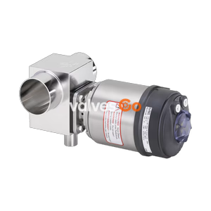
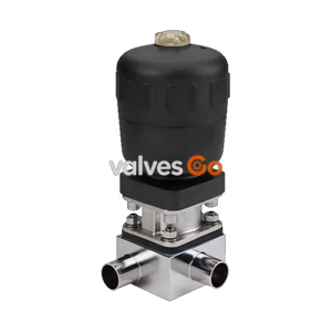
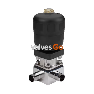
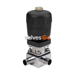
BURKERT 20087387 (Type 2933) is a 2/2-way manual diaphragm valve with DN 50 welded tube body in 1.4435 BN2 stainless steel, EPDM seal, optical position indicator, and 10 bar rating.
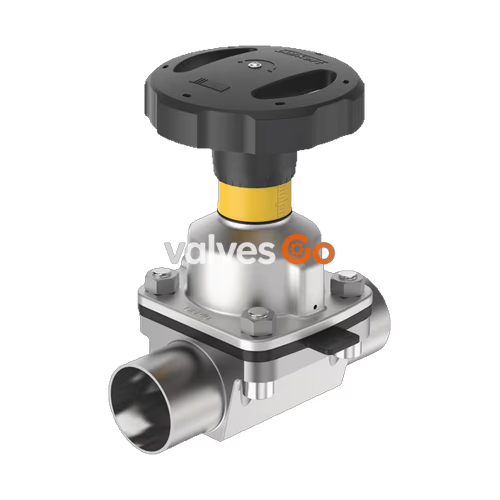
BURKERT 20087387 (Type 2933) is a manually operated 2/2-way diaphragm valve engineered for sterile, hygienic, and aggressive liquid or gas control. The valve configuration combines a flow-optimised tube valve body (VP) made of forged-equivalent stainless steel pipe 316L / 1.4435 BN2 with an autoclavable manual actuator featuring a polyphenylene sulphide (PPS) diaphragm bonnet and handwheel. Designed with diaphragm size 40 and welded pipe connections according to DIN 11850 Series 2 / DIN 11866 Series A / DIN EN 10357 Series A (53.0 x 1.5 mm, DN 50), it delivers a high water flow coefficient Kv of 46 m³/h while preventing dead zones within process lines.
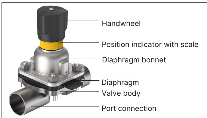
The manual actuator incorporates a built-in optical position indicator with marked scale graduations, an integrated minimum-stroke closing limiter to prevent diaphragm over-compression, and a compact housing rated for ambient temperatures up to +130 °C (short-term +150 °C). The high-temperature EPDM diaphragm handles medium temperatures from -10 °C to +143 °C and withstands steam sterilisation cycles up to +150 °C for 60 minutes.
| Parameter | Specification Details |
|---|---|
| Type | 2933 (Basic manually operated diaphragm valve) |
| Article Number | 20087387 |
| Circuit Function | 2/2-way shut-off valve |
| Nominal Diameter (DN) | DN 50 (NPS 2) |
| Diaphragm Size | 40 |
| Flow Rate Kv (Water) | 46 m³/h (Cv: 53.6 gal/min) |
| Operating Pressure Range | 0.00 bar to 10.00 bar (PN 10 / Class 150) |
| Medium Temperature Range | -10 °C to +143 °C (Steam sterilisation: max. +150 °C for 60 min) |
| Ambient Temperature Range | -10 °C to +130 °C (Short-term up to +150 °C; autoclavable) |
| Valve Body Type | Tube valve body (VP) |
| Valve Body Material | Stainless steel pipe 1.4435 BN2 / 316L (UNS S31603) |
| Port Connection 1 & 2 | Welded connection, 53.0 x 1.5 mm |
| Connection Standards | DIN 11850 R2 / DIN 11866 Series A / DIN EN 10357 Series A |
| Diaphragm Material | EPDM high-temperature (AD) |
| Bonnet & Handwheel Material | PPS (Polyphenylene sulphide) |
| Handwheel Diameter | 110 mm (Size M) |
| Position Feedback Preparation | Without electrical sensors; visual optical position indicator with scale |
| Stroke Limiter | Integrated single min-stroke limitation (closing limiter) |
| Cleaning Compatibility | CIP / SIP capable |
| Product Identification | Laser-etched Data Matrix Code |
All wetted parts comply with strict hygienic processing guidelines. The tube valve body is manufactured from certified high-alloy 316L / 1.4435-BN2 stainless steel tubing according to DIN 11866 / ASTM A269/A270 / DIN EN 10217-7. The EPDM compound AD satisfies FDA 21 CFR 177.2600, USP Class VI, and EC Regulation 1935/2004 requirements.

| Item No. | Element | Material Variant |
|---|---|---|
| 1 | Handwheel | Polyphenylene sulphide (PPS) (optional: cast stainless steel 1.4308) |
| 2 | Visual position indicator | Polyamide (PA), stainless steel 1.4305 |
| 3 | Valve spindle | Stainless steel 1.4305 |
| 4 | Diaphragm bonnet | Polyphenylene sulphide (PPS) (optional: cast stainless steel 1.4308) |
| 5 | Diaphragm | EPDM (AD) (optional: PTFE/EPDM EA, advanced PTFE EU, GYLON® ER) |
| 6 | Valve body | Stainless steel tube 1.4435 BN2 (VP) |
Body Surface Quality
Tube valve bodies (VP) are supplied with an internally electropolished surface of Ra ≤ 0.38 µm (NO17, ASME BPE SF4 / DIN HE4) and externally electropolished surface, or internally and externally glass-bead blasted Ra ≤ 1.6 µm (NO05/NO01).
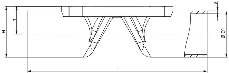
Dimensions for the welded tube valve body (VP) and actuator assembly are detailed below in mm:
| Diaphragm Size | Port Connection DN | Outer ∅ D1 [mm] | Wall Thickness s [mm] | Port Length L [mm] | Height h [mm] | Body Height H [mm] | Product Key |
|---|---|---|---|---|---|---|---|
| 8 | 10 | 13.0 | 1.5 | 90 | 9.85 | 16.35 | SD40 |
| 15 | 15 | 19.0 | 1.5 | 110 | 13.20 | 22.70 | SD42 |
| 15 | 20 | 23.0 | 1.5 | 119 | 15.20 | 26.70 | SD43 |
| 20 | 25 | 29.0 | 1.5 | 129 | 18.20 | 32.70 | SD44 |
| 25 | 32 | 35.0 | 1.5 | 148 | 21.20 | 38.70 | SD45 |
| 32 | 40 | 41.0 | 1.5 | 161 | 24.40 | 44.90 | SD46 |
| 40 (Model 20087387) | 50 | 53.0 | 1.5 | 192 | 31.70 | 58.20 | SD47 |
| Diaphragm Size | Handwheel Size | Height H1 (Open) [mm] | Height H2 (Closed) [mm] | Handwheel Diameter ∅ B [mm] | Slope per Rotation [mm] |
|---|---|---|---|---|---|
| 6 | T | 49 | 42 | 35 | 1.5 |
| 8 | T | 54 | 49 | 35 | 1.5 |
| 15 | S | 84 | 78 | 45 | 1.75 |
| 20 | S | 95 | 86 | 45 | 1.75 |
| 25 | S | 101 | 90 | 45 | 1.75 |
| 32 | M | 129 | 115 | 110 | 2.0 |
| 40 (Model 20087387) | M | 134 | 116 | 110 | 2.0 |
| 50 | M | 149 | 125 | 110 | 2.0 |
| 65 | H | 182 | 152 | 272 | 4.0 |
| 80 | H | 205 | 163 | 272 | 4.0 |
| 100 | H | 207 | 161 | 272 | 4.0 |
Applying proper fastening torque prevents external medium leakage while ensuring maximum diaphragm service life. Over-tightening can cause premature diaphragm failure.
| Diaphragm Size | Screws on Forged / Cast / Plastic Body [Nm] | Screws on Tube Body VP (EPDM/FKM) [Nm] | Screws on Tube Body VP (PTFE/GYLON®) [Nm] |
|---|---|---|---|
| 8 | 2.0 | 2.0 | 2.5 |
| 15 | 3.5 | 3.5 | 4.0 |
| 20 | 4.0 | 4.0 | 4.5 |
| 25 | 5.0 | 7.0 | 8.0 |
| 32 | 6.0 | 8.0 | 10.0 |
| 40 (Model 20087387) | 8.0 | 12.0 | 15.0 |
| 50 | 12.0 | 15.0 | 20.0 |
| 65 | 20.0 | 20.0 | 30.0 |
| 80 | 30.0 | 30.0 | 40.0 |
| 100 | 40.0 | — | — |
Torque Tolerance
A tolerance of +10% applies to all specified tightening torques. Screws must be torqued crosswise in 3 stages (approx. 1/3, 2/3, and 3/3 of the target torque).
| Diaphragm Size | Static Tightness (EPDM/FKM) [Nm] | Static Tightness (PTFE) [Nm] | Dynamic Tightness (EPDM/FKM) [Nm] | Dynamic Tightness (PTFE) [Nm] |
|---|---|---|---|---|
| 8 | 0.6 | 1.1 | 0.9 | 1.2 |
| 15 | 0.8 | 1.7 | 1.5 | 2.5 |
| 20 | 0.9 | 3.0 | 2.0 | 4.5 |
| 25 | 1.2 | 3.5 | 3.6 | 5.0 |
| 32 | 2.5 | 4.0 | 8.0 | 15.0 |
| 40 (Model 20087387) | 4.5 | 7.0 | 12.0 | 15.0 |
| 50 | 6.0 | 11.0 | 15.0 | 20.0 |
| 65 | 8.0 | 23.0 | 28.0 | 40.0 |
| 80 | 12.0 | 21.0 | 50.0 | 50.0 |
| 100 | 11.0 | 22.0 | 52.0 | 55.0 |
Type 2933 valves can be installed in any orientation; however, positioning the actuator facing upwards is preferred.
Self-Draining Installation
To guarantee complete self-draining in sanitary installations:
Turning the handwheel counterclockwise opens the valve, exposing the yellow visual indicator. The position indicator scale allows reproducible throttle adjustment (30 positions per revolution on Type 2933 Size M handwheels).
Type 2933 actuators feature an internal hexagon nut under the handwheel cap that functions as a mechanical closing limiter to protect the elastomer diaphragm from excess compression:
Stroke Limit Restriction
The minimum stroke limit is intended strictly for the 0% to 25% opening stroke range. Never position the hexagon nut within the square section of the spindle.
Under normal operating conditions following these instructions, the Type 2933 manual actuator is maintenance-free. Regular inspections of the bonnet relief bore must be conducted to detect medium weeping.

| Diaphragm Size | EPDM (AD) Article No. | FKM (FF) Article No. | PTFE/EPDM (EA) Article No. | Advanced PTFE (EU) Article No. | GYLON®/EPDM (ER) Article No. |
|---|---|---|---|---|---|
| 8 | 688 421 | 677 684 | 20093068 | 20093078 | 693 175 |
| 15 | 693 163 | 693 164 | 20093069 | 20093079 | 693 176 |
| 20 | 693 166 | 693 167 | 20093070 | 20093080 | 693 177 |
| 25 | 688 424 | 677 687 | 20093071 | 20093082 | 693 178 |
| 32 | 688 425 | 677 688 | 20093072 | 20093083 | 693 179 |
| 40 (Model 20087387) | 688 426 | 677 689 | 20093073 | 20093084 | 693 180 |
| 50 | 688 427 | 677 690 | 20093074 | 20093087 | 693 181 |
| 65 | 688 428 | 677 691 | 20093075 | 20093088 | 586 616 |
| 80 | 688 429 | 677 692 | 20093076 | 20093091 | 586 617 |
| 100 | 688 430 | 677 693 | 20093077 | 20093092 | — |
When ordered with variable code PX51, Type 2933 mechanical valves comply with ATEX and IECEx certifications for Category 2 equipment in Zones 1/21 and 2/22:
Potential Electrostatic Hazards in Ex Zones
When using valves in potentially explosive atmospheres:
Explore similar products in our catalog