


Up to 99.8% Efficiency

BURKERT 20088442 (Type 3361) is an electromotive 2-way globe control valve with AG3 10000 N actuator, DN 80 welded ends, PTFE seat seal, Kvs 100 m3/h, 24 V DC power supply, and integrated positioner.
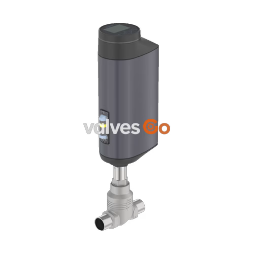
BURKERT 20088442 (Type 3361) is an electromotive 2-way globe control valve engineered for precise process control tasks under demanding operating conditions. The assembly combines a stainless steel globe valve body with an AG3 electromotive linear actuator that delivers a nominal positioning force of 10,000 N via a ball screw drive. Port connections are configured as welded ends DN 80 (NPS 3) with pipe dimensions of 85.0 x 2.0 mm conforming to DIN 11850-2, DIN 11866 series A, and DIN EN 10357 series A. The valve seat has a nominal diameter of 80 mm, providing a rated flow coefficient of Kvs 100 m³/h (Cv 115.6 gpm) with an equal-percentage 50:1 flow characteristic.
Operating with a positioning dead band of ±0.1% and a linear travel speed of 3 mm/s, the AG3 actuator achieves a typical closing time of 12.0 s. The unit is supplied in normally closed (NC) status and includes an internal SAFEPOS energy-pack emergency storage module that drives the valve to the fail-safe closed position upon supply voltage failure. Fluid control is directed against closing direction (flow below seat), and sealing integrity complies with DIN EN 60534-4 leakage class VI using a PTFE seat seal washer. Operator interface and commissioning are facilitated through a rugged display module with push buttons, a 360° LED illuminated ring for visual status indication, and a service büS interface compatible with the Bürkert Communicator software Type 8920.

| Specification Parameter | Value / Range |
|---|---|
| Valve Type | Electromotive 2-way globe control valve (Type 3361) |
| Article Number | 20088442 |
| Actuator Size & Driving Force | AG3 (10,000 N linear electromotor) |
| Nominal Diameter | DN 80 (NPS 3) |
| Port Connection Type | Welded ends (tube 85.0 x 2.0 mm) |
| Connection Standards | DIN 11850-2 / DIN 11866 series A / DIN EN 10357 series A |
| Valve Seat Diameter | 80 mm (3") |
| Flow Coefficient | Kvs = 100 m³/h (Cv = 115.6 gpm) |
| Flow Characteristic | Equal percentage, theoretical rangeability 50:1 |
| Operating Pressure Range | 0 to 21 bar(g) (12.5 bar(g) for group 1 compressible fluids per 97/23/EC) |
| Nominal Pressure Class | PN 25 (DIN EN 1333), Class 150 (DIN EN 1759) |
| Flow Direction | Below seat (against closing direction, 2 → 1) |
| Seat Leakage Class | Class VI according to DIN EN 60534-4 |
| Medium Temperature Range | -10 °C to +130 °C (PTFE seat seal limit) |
| Ambient Temperature Range | -25 °C to +65 °C (derated with display / SAFEPOS modules) |
| Operating Voltage | 24 V DC ±10% (maximum residual ripple 10%) |
| Operating Current | Maximum 5 A (at maximum load including SAFEPOS charging current); +6 A at min. operating temp. |
| Standby Power Consumption | 2 to 5 W |
| Travel Speed | 3 mm/s (AG3 driving force 10,000 N) |
| Typical Closing Time | 12.0 s (AG3 total travel range 8.7 to 12.0 s) |
| Position Control Dead Band | ±0.1% |
| Duty Cycle | 100% continuous |
| Protection Class (DIN EN 61140) | III |
| Enclosure Rating | IP65 / IP67 (DIN EN 60529), NEMA 4X |
| Permissible Fluid Viscosity | Up to 600 mm²/s |
| Weight | AG3 actuator approx. 16 kg (excluding valve body) |
| Installation Position | Any, preferably upright with actuator above the valve body |
All media-wetted components comply with EC Regulation 1935/2004 and FDA regulations. The spindle packing utilizes self-adjusting PTFE V-rings energized by a spring compensation mechanism.
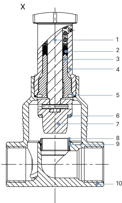
| Item | Component | Material |
|---|---|---|
| 1 | Spindle | Stainless steel 1.4401 (316) / 1.4404 (316L) |
| 2 | Spindle seal | PTFE V-seals (filled) with spring compensation |
| 3 | Spindle guide | Stainless steel 1.4404 (316L) |
| 4 | Packing gland tube | Stainless steel 1.4401 (316) |
| 5 | Valve body seal | Graphite or PTFE |
| 6 | Seat seal | PTFE seal washer (soft sealing, leakage Class VI) |
| 7 | Control cone | Stainless steel 1.4571 (316Ti) |
| 8 | Valve seat | Stainless steel 1.4571 (316Ti) |
| 9 | Valve seat O-ring | EPDM or PTFE |
| 10 | Valve body | Stainless steel CF3M (cast equivalent to 316L) |
| Item | Actuator Component (AG3) | Material |
|---|---|---|
| 1 | Display housing / blind cover | Polyphenylene sulfide (PPS) |
| 2 | Actuator cover | Polycarbonate (PC) |
| 3, 6 | Housing seals | EPDM |
| 4 | Actuator housing | Aluminium, powder-coated |
| 5 | SAFEPOS energy-pack housing | Polycarbonate (PC) |
| 7 | Actuator base | Stainless steel 1.4308 |
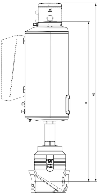
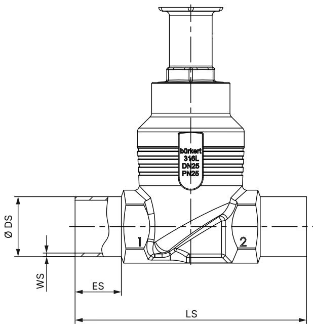
Installation Recommendation
The valve can be mounted in any orientation. Mounting upright with the actuator positioned vertically above the valve body is recommended to ensure optimal drainage, reduced particulate accumulation in the packing gland, and convenient display visibility.
Article 20088442 utilizes an analogue control architecture with M12 circular connectors located on the AG3 actuator base. Supply power and control signals are routed through dedicated plugs.
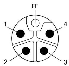
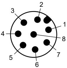
| Pin | Signal Assignment | Electrical Specification |
|---|---|---|
| 1 | Digital input + | 0 to 5 V = log "0", 10 to 30 V = log "1" |
| 2 | GND | Common ground for digital input and digital outputs |
| 3 | Digital output 2 + | PNP transistor output, max. current limit 100 mA |
| 4 | Digital output 1 + | PNP transistor output, max. current limit 100 mA |
| 5 | Analogue output - | Galvanically isolated reference |
| 6 | Analogue output + | 0/4 to 20 mA (load 0 to 800 Ω) or 0 to 5/10 V (max. 10 mA) |
| 7 | Set-point / Analogue input - | Galvanically isolated reference |
| 8 | Set-point / Analogue input + | 0/4 to 20 mA (input resistance 70 Ω) or 0 to 5/10 V (22 kΩ) |
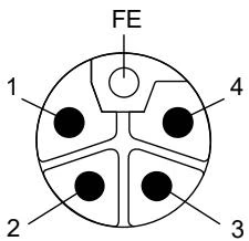
| Pin | Assignment | Function |
|---|---|---|
| 1 | Operating voltage + | 24 V DC ±10% |
| 2 | Not connected | - |
| 3 | GND | Power supply ground |
| 4 | Not connected | - |
| FE | Functional earth | Connected directly to valve body and actuator housing |
The DN 80 globe body with seat diameter 80 mm features an equal-percentage characteristic curve calibrated according to DIN EN 60534-2-4 with a rangeability of 50:1.
| Stroke (%) | 5% | 10% | 20% | 30% | 40% | 50% | 60% | 70% | 80% | 90% | 100% (Kvs) |
|---|---|---|---|---|---|---|---|---|---|---|---|
| Kv (m³/h) | 2.1 | 2.6 | 4.2 | 7.0 | 10.5 | 16.0 | 25.0 | 40.0 | 60.0 | 83.0 | 100.0 |
Pressure and Temperature Operating Limits
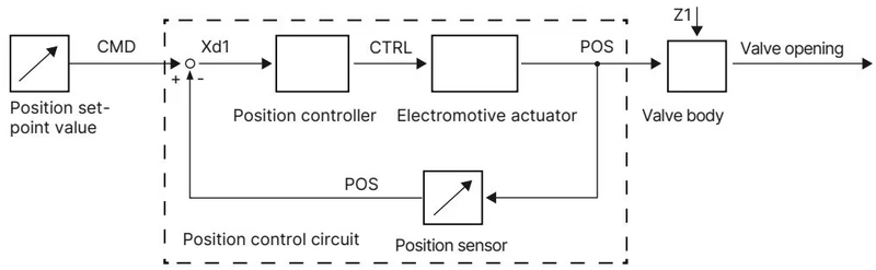

The positioning system compares the external command signal (CMD, analogue 0/4 to 20 mA or 0 to 5/10 V) with the internal position feedback (POS) measured by a contactless displacement transducer on the motor spindle. If a control deviation (Xd1) exists, the motor drive adjusts the spindle stroke via the manipulating variable CTRL until the target position is reached.
The plug-in SAFEPOS energy-pack provides fail-safe positioning during a supply power interruption. The internal storage device charges completely in less than 120 seconds during initial energization and retains an operating life up to 10 years depending on operating temperature. Upon power failure, the energy pack drives the actuator to the programmed safety position (factory default: fully closed).
Pressure and Voltage Hazard
Before opening or servicing the valve assembly, isolate the pipeline, vent process pressure, completely drain the media, and switch off the 24 V DC supply voltage. Completely discharge the SAFEPOS energy-pack and verify that the 360° LED ring has turned completely off.
Prevent Sealing Damage
During actuator removal or reinstallation, the valve must be driven to at least 1/3 open or fully open position. Unscrewing the actuator while the valve cone is pressed tightly into the seat will shear the PTFE seal washer and damage the cone contour.
Calibration Requirement
Run the X.TUNE routine whenever the actuator has been remounted, the control cone replaced, or the valve seat changed. Never execute X.TUNE while medium pressure is applied to the pipeline.
Explore similar products in our catalog


