Type 2032

BURKERT Type 2935 (SKU 20089832) manual tank bottom diaphragm valve. Features DN 65 flange, PTFE/EPDM diaphragm, PPS actuator, and ATEX/IECEx approvals.
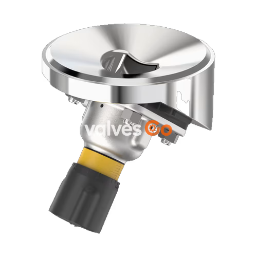
BURKERT Type 2935 (SKU 20089832) is a manually operated diaphragm valve consisting of a manual actuator, a PTFE/EPDM diaphragm, and a stainless steel tank bottom valve body. The manual actuator features a PPS (Polyphenylene sulphide) handwheel and bonnet, ensuring reliable use in hygienic or aggressive ambient conditions. The flow-optimized tank bottom body with minimum dead space enables high flow values and is ideal for highly purified, sterile, or aggressive media. The actuator has a compact, autoclavable design and is equipped with an integrated visual position indicator, a reproducible stroke scale, and a single min-stroke limiter (closing limiter).
This specific model features a DN 65 Bürkert-tank bottom flange for the primary connection and a 19.05 x 1.65 (Cl: 25.0) secondary port connection, utilizing a size 15 diaphragm. It is fully CIP and SIP capable, making it suitable for pharmaceutical and food & beverage applications.
The Type 2935 valve is designed to meet stringent industry standards:
| Element | Material |
|---|---|
| Handwheel | Polyphenylene sulphide (PPS) |
| Visual position indicator | Polyamide (PA), stainless steel 1.4305 |
| Valve spindle | Stainless steel 1.4305 |
| Diaphragm bonnet | Polyphenylene sulphide (PPS) |
| Diaphragm | PTFE with EPDM backing membrane |
| Valve body | Stainless steel block material 1.4435 (DIN EN 10088) and 316L (ASME BPE) |
By manually overriding the handwheel, the force is transmitted via a spindle and the valve is opened or closed. Turning the handwheel anticlockwise opens the valve, turning it clockwise closes it.
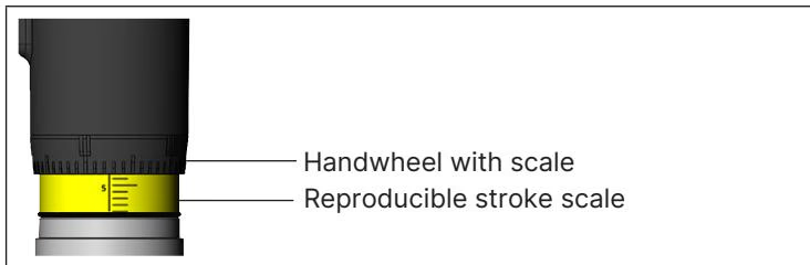
Turning the handwheel counterclockwise reveals the yellow position indicator and the scale marked on it as the valve opens further. The scale on the handwheel determines the rotation position of the handwheel (30 positions for Type 293x). The stroke scale shows the relative position of the valve and serves as a fixation point for determining the rotation position.
WARNING
To protect the actuator, do not close the actuator with more force than is required to close the valve tightly. The visibility of the yellow mark is not directly correlated with the closed position of the valve.
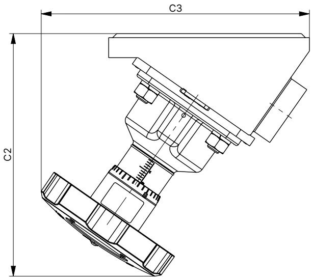
| Diaphragm size | C2 [mm] | C3 [mm] |
|---|---|---|
| 15 | 103 | 101 |
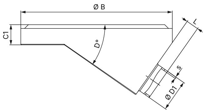
(Note: Dimensions vary based on the specific pipe standard. Refer to the full datasheet for comprehensive welded connection tables across DIN, ISO, and ASME BPE standards.)
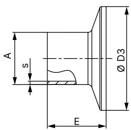
(Note: Clamp dimensions must be added to the welded connection dimensions.)
DANGER
Risk of injury due to high pressure and escaping medium. Switch off the pressure before working on the device or system. Vent or empty the lines.
Recommendations for welding sequence:
TIP
For information on containers and instructions for welding, refer to the ASME VIII Division I standard. Check the batch number indicated on the manufacturer’s certificate 3.1 supplied before starting welding work.
Preparatory Work: The actuator and diaphragm must be dismantled before welding or bonding the valve body.
A minimum stroke limit can be set for Type 2935. This setting also serves as a closing limiter to protect the diaphragm. A hexagon nut is used to do this.
WARNING
Damage to the device by incorrectly positioning the hexagon nut. Do not screw the hexagon nut in the area of the square. Only use minimum stroke limit in the 0…25 % opening stroke range.
The actuator of the diaphragm valve is maintenance-free when used in accordance with the operating instructions. However, the diaphragm is a wear part.
Replacing the Diaphragm (Size 15 - Bayonet Catch):
Explore similar products in our catalog