

PN16

BURKERT 20091551 is a Type 8652 AirLINE 24-station pneumatic valve island featuring Industrial Ethernet, 24 5/3-way CF-N valves, aluminium AirLINE Quick plate, -1 to 10 bar operating pressure, and cULus listing.
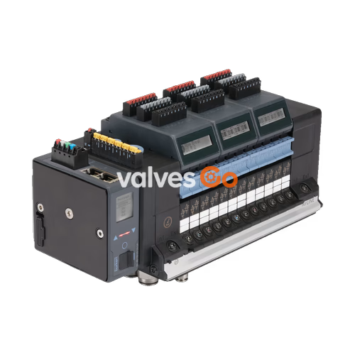
BURKERT 20091551 (Type 8652 AirLINE) is a 24-station pneumatic valve island engineered for process automation, pre-assembled on an anodised aluminium AirLINE Quick adapter plate. It is equipped with Industrial Ethernet communication supporting PROFINET IO, EtherNet/IP, Modbus TCP, EtherCAT, and CC-Link IE Field Basic over dual RJ45 ports, operating on a 24 V DC supply with an IP20 ingress protection rating.

All 24 valve positions are populated with 5/3-way servo-controlled solenoid valves with circuit function CF-N (middle position ventilated/exhausted). The unit integrates an intermediate pneumatic feed module to ensure uniform air delivery across high-density valve banks, utilizing push-in brass connectors sized at D10 mm for main air supplies and D6 mm for process actuator lines.
Article 20091551 provides a fully equipped 24-slot pneumatic block. Each station utilizes an 11 mm width Type 6534 pilot valve assembly with manual override.
| Specification Parameter | Value / Assignment |
|---|---|
| Number of Valve Slots | 24 PCE |
| Valve Positions 1 to 24 | 5/3-way middle position ventilated CF-N (Type 6534) |
| Modular Variant | Fieldbus module with ME43 architecture |
| Supply Connection Port Size | Push-in connector D10 mm |
| Supply Connection Material | Brass |
| Working Port Size (2 and 4) | Push-in connector D6 mm |
| Working Port Material | Brass |
| AirLINE Quick Plate Material | Anodised aluminium |
| Auxiliary Pilot Air | Internal (pilot pressure 3 to 10 bar) |
| Intermediate Supply Left | Push-in connectors D6 and D10 |
| Intermediate Supply Middle | Push-in connectors D6 and D10 |
| Intermediate Supply Right | Without additional supply |
| Intermediate Feed Quantity | 1 PCE integrated between valve blocks |
| Digital Input Modules (DI) | 0 (El. modules 1 through 6 not fitted) |
| Integrated Check Valves | None in duct 3 (R) or 5 (S) |
| Pneumatic HotSwap in Port 1 (P) | No |
Every valve position from slot 1 through slot 24 operates with circuit function N. In the de-energised middle position, working ports 2 and 4 are vented to atmosphere through the exhaust channels. Each valve station provides a nominal air flow rate QNn of 300 l/min at 6 bar supply pressure and 1 bar differential pressure.
| Category | Parameter | Source Specification |
|---|---|---|
| Operating Pressures | Nominal Pressure Range | Vac to 10 bar (-1.0 bar to 10.0 bar) |
| Pilot Pressure (Auxiliary) | 3.0 bar to 10.0 bar | |
| Flow Capacity | Nominal Flow Rate QNn (Air) | 300 l/min (CF-N, measured according to ISO 12238) |
| Electrical Specifications | Operating Voltage | 24 V DC (±10 % tolerance, residual ripple 1 Vss) |
| Nominal Power per Valve | 0.7 W initial pick-up (0.175 W after electronic power reduction) | |
| Nominal Current per Valve | 29 mA pick-up (10 mA holding current after reduction) | |
| Electrical Protection Class | Class III according to DIN EN 61140, VDE 0140 | |
| Nominal Operating Mode | Continuous operation (100 % duty cycle) | |
| Fluid Media | Operating Medium | Compressed dry air (lubricated or unlubricated), neutral gases |
| Quality Class | ISO 8573-1: 2010, Class 7.4.4 (5 µm pre-filtering recommended) | |
| Temperature Limits | Medium Temperature | -10 °C to +55 °C |
| Ambient Operating Temperature | -10 °C to +55 °C | |
| Storage Temperature | -20 °C to +60 °C | |
| Materials | Valve Body | PA (Polyamide) |
| Seals | NBR and PUR | |
| AirLINE Quick Adapter Plate | Anodised aluminium | |
| Pneumatic Connectors | Brass | |
| Enclosure & Standards | Ingress Protection | IP20 (IP65 when installed in sealed control cabinet) |
| Certification | cULus Listed (UL 61010-1, CAN/CSA-C22.2 No. 61010-1) |
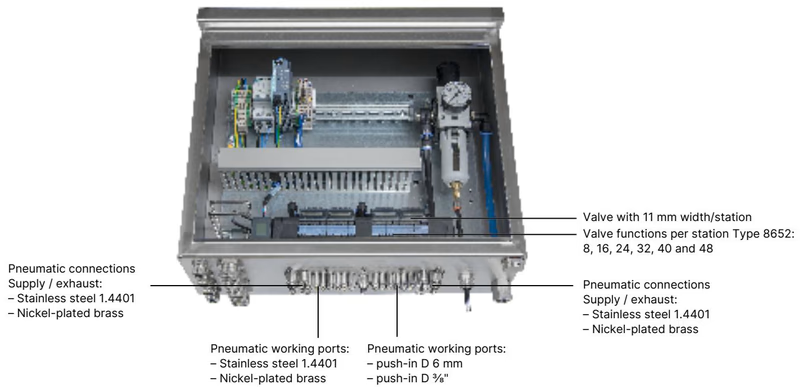
The AirLINE Quick adapter interface attaches directly into cutouts in the control cabinet floor or wall. By routing all pneumatic connections through an anodised aluminium bottom plate, external bulkhead couplings and internal interconnecting tubing are eliminated.
| AirLINE Quick Feature | Specification for Article 20091551 |
|---|---|
| Adapter Plate Material | Anodised aluminium |
| Pneumatic Supply / Exhaust Ports | Push-in connector D10 mm, brass |
| Pneumatic Working Ports | Push-in connector D6 mm, brass |
| Mounting Orientation | Control cabinet floor or control cabinet wall |
| Space Savings | Replaces individual bulkhead fittings; enables compact cabinet envelopes |
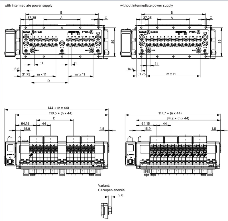
Article 20091551 corresponds to the 24-fold pneumatic valve island variant configured with an intermediate supply module.
| Dimension Variable | Source Value (mm) | Description |
|---|---|---|
| A | 156 mm | Distance to first mounting coordinate group |
| B | 312 mm | Total longitudinal mounting center span |
| C | 10 x M5 | Fastening thread specification for cabinet base mounting |
| D | 158.3 mm | Intermediate supply module location offset |
| m | 11 | Number of valve stations in primary block |
| m' | 11 | Number of valve stations in secondary block |
| n | 6 | Structural support rib index |
| Station Width | 11 mm per station | Pitch per pneumatic valve slot |
Control Cabinet Installation
When mounting the valve terminal to the control cabinet base, use the dedicated M5 x 10 A2 DIN 6912 screw sets (Article no. 308661). Ensure sufficient clearance to the front door and rear wall of the enclosure to permit clear visibility of the LC display and unobstructed access to pneumatic tubing.
Electrical connections are separated into distinct supply paths for communication/display logic and solenoid coil actuation.
Logic power and internal büS communication are connected via a 5-pin spring-loaded terminal connector (conductor cross-section ≤ 1.5 mm²):
| Terminal | Lead Colour | Pin Assignment |
|---|---|---|
| 1 | Red | +24 V DC (Logic Supply) |
| 2 | White | CAN_H (büS connection) |
| 3 | Green | SHIELDING |
| 4 | Blue | CAN_L (büS connection) |
| 5 | Black | GND (Logic Ground) |
The interface plate incorporates a dedicated 2-pin spring-loaded terminal for solenoid coil power:
| Terminal Pin | Clip Identifier | Lead Colour | Assignment |
|---|---|---|---|
| 1 | Clip 1 | Red | AUX +24 V DC (Valve Power) |
| 2 | Clip 2 | Black | GND (Valve Ground) |
The fieldbus interface accommodates Industrial Ethernet networks (PROFINET IO, EtherNet/IP, Modbus TCP, EtherCAT, CC-Link IE Field Basic) via dual RJ45 sockets:
| RJ45 Pin | Signal Assignment | Functional Description |
|---|---|---|
| Pin 1 | TX+ | Transmit Data positive |
| Pin 2 | TX- | Transmit Data negative |
| Pin 3 | RX+ | Receive Data positive |
| Pin 4 | N.C. | Not connected |
| Pin 5 | N.C. | Not connected |
| Pin 6 | RX- | Receive Data negative |
| Pin 7 | N.C. | Not connected |
| Pin 8 | N.C. | Not connected |
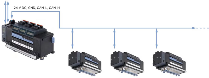
Industrial Ethernet Communication
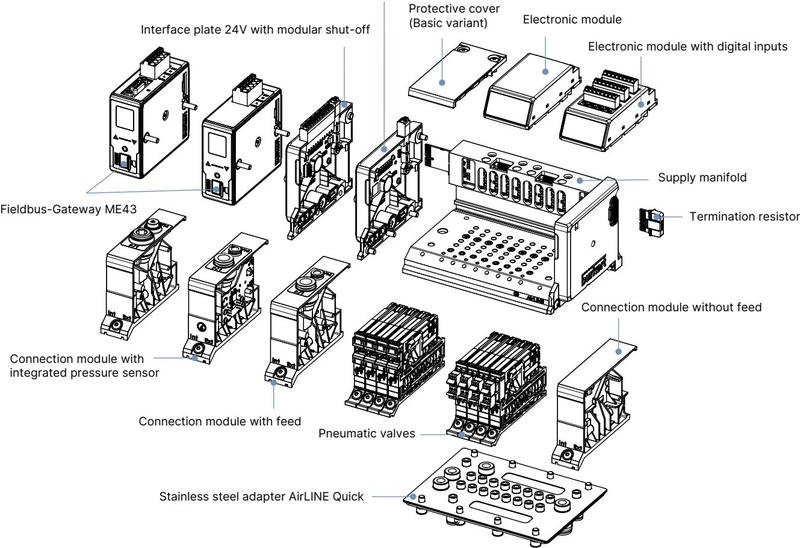
The onboard ME43 gateway architecture allows the Type 8652 valve island to function as an Industrial Ethernet master island, networking downstream büS/CANopen valve islands or sensors within a centralized cabinet topology. Protocol parameter files must be loaded via the Bürkert Communicator software Type 8920 prior to plant start-up.
Each valve slot on article 20091551 accepts modular Type 6534 solenoid valves. While all 24 slots are factory fitted with circuit function N, other functions can be interchanged on the manifold sub-base:
| Circuit Function | Valve Type | QNn Air [l/min] | Pressure Range [bar] | Opening / Closing Time [ms] | Article No. (incl. screw) | Spare Part Set Article No. |
|---|---|---|---|---|---|---|
| CF N | 5/3-way, middle position exhausted | 300 | Vac to 10 | 20 / 20 | 301381 | REF_296039 |
| CF M | 5/3-way, middle position ventilated | 300 | Vac to 10 | 20 / 20 | 301379 | REF_296035 |
| CF L | 5/3-way, middle position closed | 275 | Vac to 10 | 15 / 15 | 301380 | REF_296036 |
| CF H | 5/2-way servo-controlled | 290 | Vac to 10 | 20 / 25 | 301376 | REF_296033 |
| CF Z | 5/2-way impulse (bistable) | 290 | Vac to 10 | 20 / 25 | 301377 | REF_296034 |
| CF C | 3/2-way NC servo-controlled | 270 | Vac to 10 | 15 / 15 | 20102334 | REF_20088974 |
| CF C | 2 x 3/2-way NC servo-controlled | 270 | Vac to 10 | 15 / 15 | 301374 | REF_296031 |
| CF D | 2 x 3/2-way NO servo-controlled | 310 | Vac to 10 | 15 / 15 | 301375 | REF_296032 |
| Dummy | Blanking plate for unused station | - | - | - | 335779 | REF_327614 |
| Accessory Description | Configuration | Quantity | Article No. |
|---|---|---|---|
| AirLINE Quick Height Adapter | 24-fold with intermediate feed | 1 PCE | 754964 |
| AirLINE Quick Retaining Plate | 24-fold with intermediate feed (cabinet exterior) | 1 PCE | 60005570 |
| AirLINE Quick Blind Plate | 24-fold with intermediate feed | 1 PCE | 754969 |
| Mounting Screw Set | M5 x 10 A2 DIN 6912 (cabinet base fastening) | 10 PCE | 308661 |
| 5-Pin Spring-Loaded Terminal | Logic & büS power supply connector | 1 PCE | 920180 |
| 2-Pin Spring-Loaded Terminal | Solenoid valve power supply connector | 1 PCE | 920442 |
| USB büS Interface Set 1 | Type 8923 with M12/micro-USB cables and power supply | 1 SET | 772426 |
| USB büS Interface Set 2 | Type 8923 with M12 connection cable, Y-distributor | 1 SET | 772551 |
Article 20091551 is certified as cULus Listed under standards UL 61010-1 and CAN/CSA-C22.2 No. 61010-1 for general electrical measurement and control equipment.
Hazardous Area Application Notice
When Type 8652 valve islands are supplied with explosion protection options (such as order codes PU17 or PX68 for ATEX/IECEx Zone 2/22 or cURus HazLoc Class I Div 2), electrical terminals and Hot Swap connections must never be connected or disconnected while energized unless the surrounding atmosphere is confirmed to be non-hazardous. For Zone 2 (gas) installations, the assembly must reside in an enclosure rated at least IP54; for Zone 22 (dust), the enclosure rating must be at least IP6X.
Explore similar products in our catalog


