

PN16

BURKERT 20092303 (Type 8652) is an 8-slot AirLINE pneumatic valve island with Industrial Ethernet, brass D10/D6 ports, and Type 6534 pilot valves for automated industrial pneumatic control.
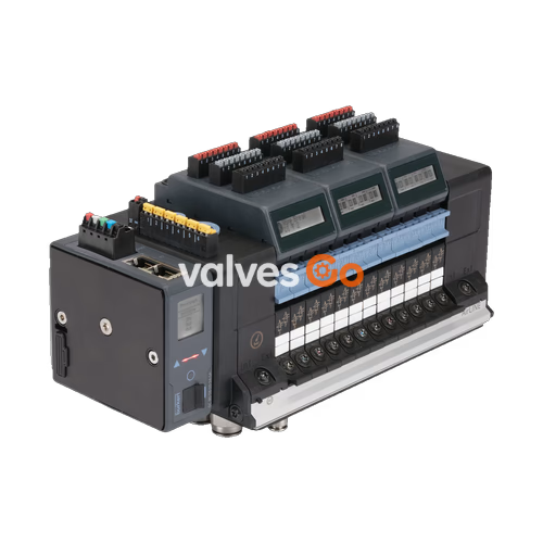
BURKERT 20092303 (Type 8652 AirLINE) is an 8-slot modular electro-pneumatic valve island designed to actuate pneumatic loads in process and factory automation systems. Built on an aluminium AirLINE Quick base plate, this unit integrates an Industrial Ethernet fieldbus communication module with an RJ45 hardware interface, supporting PROFINET IO, EtherNet/IP, Modbus TCP, EtherCAT, and CC-Link IE Field Basic network architectures. Brass push-in fittings accommodate a D10 main supply line and D6 process working lines, operating within a nominal pneumatic pressure span from -1.00 bar to 10.00 bar.
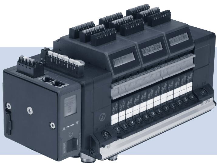
The internal pilot air circuit functions between 3.00 bar and 10.00 bar. The electrical system runs on a 24 V DC supply with a nominal current consumption of 3 A. The pneumatic section incorporates Type 6534 pilot-operated spool valves driven by Type 6164 miniature solenoid pilots. The valve configuration comprises six standard 2x 3/2-way valve modules and two SIA safety-related valve modules that provide external electrical valve shut-off capability.
Article 20092303 is supplied as a factory-assembled 8-bank configuration without intermediate pneumatic feed blocks or digital input expansion modules. Valve positions 1 through 6 carry double 3/2-way normally closed valves (circuit function C), while positions 7 and 8 provide double 3/2-way valves equipped with SIA circuitry.
| Valve Position | Valve Module Description | Circuit Function | Safety Shut-off (SIA / EVS) |
|---|---|---|---|
| Position 1 | 2x 3/2-way pneumatic valve (Type 6534) | CF-C (Normally Closed) | Standard |
| Position 2 | 2x 3/2-way pneumatic valve (Type 6534) | CF-C (Normally Closed) | Standard |
| Position 3 | 2x 3/2-way pneumatic valve (Type 6534) | CF-C (Normally Closed) | Standard |
| Position 4 | 2x 3/2-way pneumatic valve (Type 6534) | CF-C (Normally Closed) | Standard |
| Position 5 | 2x 3/2-way pneumatic valve (Type 6534) | CF-C (Normally Closed) | Standard |
| Position 6 | 2x 3/2-way pneumatic valve (Type 6534) | CF-C (Normally Closed) | Standard |
| Position 7 | 2x 3/2-way pneumatic valve (Type 6534 SIA) | CF-C (Normally Closed) | External Valve Shut-off (EVS) |
| Position 8 | 2x 3/2-way pneumatic valve (Type 6534 SIA) | CF-C (Normally Closed) | External Valve Shut-off (EVS) |
External Valve Shut-off (EVS) and SIA Functionality
EVS functionality allows specific pneumatic valves, sub-banks, or the entire valve island to be de-energized independently of the industrial fieldbus master control signal. Slots 7 and 8 in this unit utilize SIA-configured hardware to execute safe electrical disconnection of pilot valve coils during safety-related shutdown conditions.
The manifold assembly relies on internal pilot air routed from port 1, removing the need for an external auxiliary pilot line. Check valves in exhaust lines 3 (R) and 5 (S) are not fitted on this configuration. Working lines feature brass D6 push-in connectors, and the supply port features a brass D10 connector.
| Parameter | Source Specification | Remarks |
|---|---|---|
| Total Valve Slots | 8 PCE | Fixed factory assembly |
| Nominal Working Pressure | -1.00 bar to 10.00 bar | Port 1 (P) |
| Auxiliary Pilot Pressure | 3.00 bar to 10.00 bar | Internal pilot routing |
| Supply Port 1 (P) | D10 push-in connection | Brass material |
| Working Ports 2 and 4 | D6 push-in connection | Brass material |
| Base Plate Mounting Interface | AirLINE Quick | Aluminium plate |
| Additional Air Supply Ports | None | Left, middle, and right feeds absent |
| Medium Temperature | -10.00 °C to 55.00 °C | Neutral gases, dry compressed air |
| Ambient Operating Temperature | -10.00 °C to 55.00 °C | Inside control cabinet |
| Ingress Protection Rating | IP20 | Maximum with matching connectors |
| Integrated Check Valves | None | Exhaust ports 3 (R) and 5 (S) open |
| Pneumatic HotSwap in Port 1 | No | Standard valve base plate |
Communication is processed through an integrated fieldbus module utilizing a dual RJ45 Ethernet hardware interface. Network protocols are selectable across major industrial standards, enabling integration into decentralized control networks.
When ordered under hazardous area codes PU17 or PX68, Type 8652 valve islands comply with ATEX Directive 2014/34/EU, IECEx schemes, and NEC regulations for Zone 2 and Zone 22 applications.
Hazardous Area Installation and HotSwap Restrictions
For Type of Protection "ec" (gas), the equipment must be mounted in an enclosure providing at least IP54 per EN/IEC 60079-0 and EN/IEC 60079-7. For Type of Protection "tc" (dust), the enclosure must provide at least IP6X per EN/IEC 60079-31. Use is permitted only in areas of pollution degree 2 or better according to IEC 60664-1.
Terminals for 24 V DC power, SIA, EVS, and digital inputs must only be connected or disconnected when the circuit is de-energized, unless the area is verified to be non-hazardous. HotSwap replacement of pneumatic valves is prohibited in hazardous explosive atmospheres unless tested and certified to be free of explosive gas mixtures.
Enclosure Sizing and Thermal Dissipation
At an internal cabinet ambient temperature of +55 °C, surface temperatures comply with temperature class T4. When using the aluminium AirLINE Quick base plate, the exterior mounting interface temperature does not exceed 80 °C under continuous operation. The host control cabinet must have sufficient surface area or ventilation to dissipate internal heat losses.
Type 8652 valve islands approved for explosive atmospheres feature two nameplates: a standard identification label and an Ex approval plate.
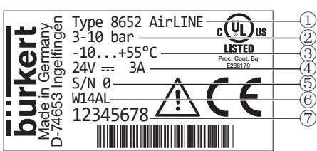
| Position | Description | Example Data |
|---|---|---|
| 1 | Device Type | Type 8652 AirLINE |
| 2 | Pressure Range | 3 to 10 bar |
| 3 | Ambient Temperature Range | -10 °C to +55 °C |
| 4 | Rated Voltage / Current Consumption | 24 V DC / 3 A |
| 5 | Serial Number | S/N (sequential) |
| 6 | Manufacturing Code | Date code |
| 7 | Device Order Number (Article / Ident) | 20092303 |
Units coded PX68 display ATEX and IECEx Zone 2/22 approval data, while units coded PU17 include both North American Class/Division/Zone markings and European approvals.
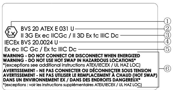
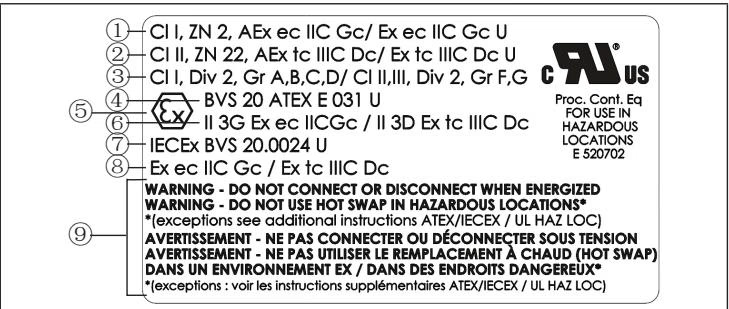
Each delivery contains an additional adhesive label stating: "WARNING DO NOT CONNECT OR DISCONNECT WHEN ENERGIZED". If the primary Ex nameplate is obscured after cabinet wall mounting, this warning label must be placed in a clearly visible position on the outer assembly.
Explore similar products in our catalog


