

PN16

BURKERT 20099403 (Type 8647 AirLINE SP) is an 8-bank pneumatic valve island with 11 mm width per station, G 1/4 supply, D6 working ports, HotSwap, check valves, and Siemens ET 200SP integration.
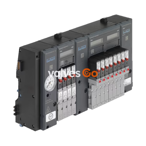
BURKERT 20099403 is an 8-bank pneumatic valve island belonging to the Type 8647 AirLINE SP electropneumatic automation system family, built for direct integration into Siemens SIMATIC ET 200SP and ET 200SP HA distributed I/O systems. Operating on an 11 mm width per station grid, this Revision 2 (REV.2) assembly features a mixed valve population with 3/2-way pilot functionality, G 1/4 primary supply ports, and bottom-oriented push-in D6 working ports. The unit incorporates integrated check valves in exhaust ducts 3 (R) and 5 (S), as well as pneumatic HotSwap non-return functionality in channel 1 (P).
Engineered for process plant automation, the assembly mechanically and electrically docks to standard DIN mounting rails directly adjacent to Siemens ET 200SP electronic base units. Pilot solenoid valves control actuators, hygienic process valves, and pneumatic cylinders while feeding visual feedback into dedicated graphic LC displays and backplane fieldbus registers. The assembly carries ATEX and IECEx Zone 2 approvals for industrial hazardous atmosphere deployment.
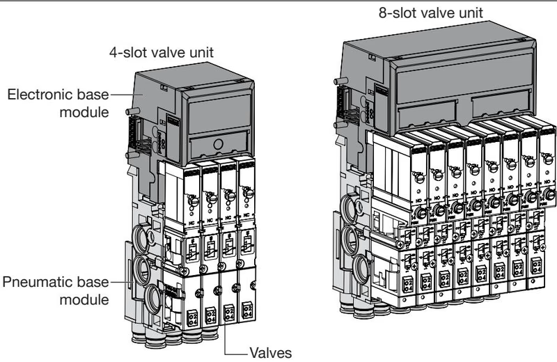
Type 8647 AirLINE SP merges electrical signal processing and pneumatic actuation into a single rack format. The valve island consists of lateral connection units (PSU), electronic base modules (PQ), pneumatic base modules, and plug-in pilot solenoid valves. Power and communication lines link through the Siemens ET 200SP backplane bus without external inter-module wiring.
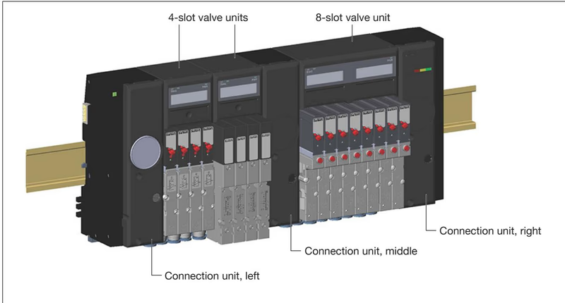
Key integration properties include:
Article 20099403 is manufactured to the Revision 2 (REV.2) hardware architecture. REV.2 introduces structural pneumatic optimizations that differentiate it from early REV.1 models:
| Distinguishing Feature | Revision 1 (REV.1) | Revision 2 (REV.2) — Model 20099403 |
|---|---|---|
| Release ring colour on push-in connectors | Black | Blue |
| Working connection channel arrangement | Parallel alignment | Wavy offset alignment |
| Pilot valve pneumatic flange pattern | Separate FM14 (single) and FM20 (double) | Unified FM20 interface across single and double valves |
| Flow restriction with integrated P-shutoff (HotSwap) | Reduction up to 50% | Reduction approx. 20% |
| Type label identification | Without "Rev." marking | Explicitly marked "Rev.2" |
Flange Interface Compatibility Restriction
Single valves from REV.1 (FM14 flange pattern) and REV.2 (FM20 flange pattern) are mechanically non-interchangeable. When replacing pilot valves on 20099403, only REV.2 certified valves with FM20 pattern or double valves may be fitted.
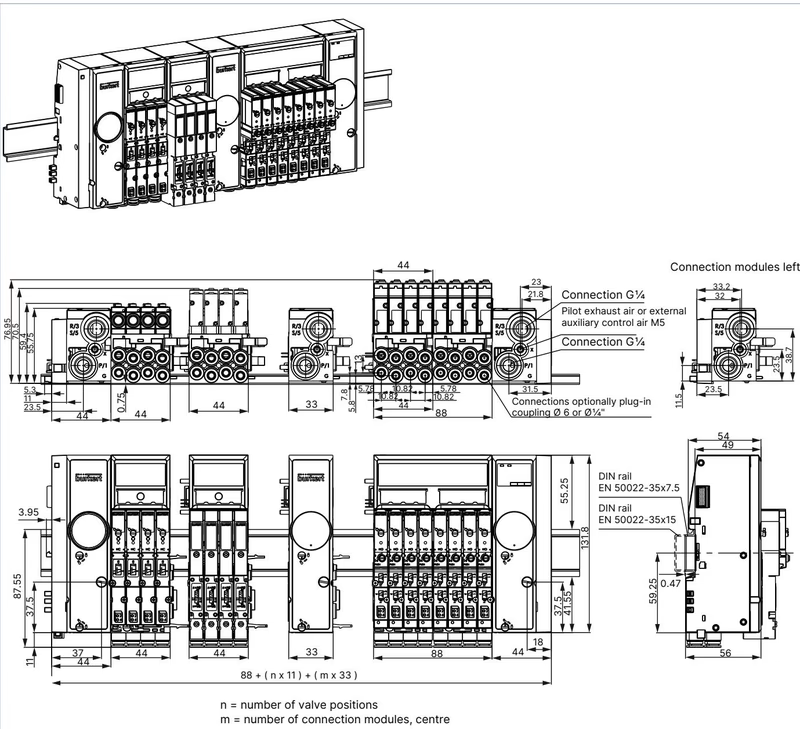
Type 8647 consists of functional blocks assembled side-by-side along the DIN rail:
| Parameter | Technical Specification |
|---|---|
| Grid spacing (Width per station) | 11 mm |
| Total valve stations | 8 valve slots |
| Valve functions supported | Mixed (Type 6524 3/2-way, 2×3/2-way, Type 6525 5/2-way, Type 0460 5/2 & 5/3) |
| Operating pressure range | 2.5 to 10.0 bar (Vac. to 8 bar under UL, external pilot >2.5 bar) |
| Flow rate QNn (Air) | 200 to 300 l/min (at 6 bar inlet, 1 bar differential pressure) |
| Operating voltage | 24 V DC (±10%, SELV/PELV, max. 2.4 Vss ripple) |
| Power consumption per valve | 0.8 W (single), 2 × 0.8 W (double valve with power reduction) |
| Nominal current per valve | 40 mA pick-up (holding current drops to 28 mA after 120 ms) |
| Compressed air quality | ISO 8573-1:2010 Class 7.4.4 (filtered to 5 µm, dry, lubricated or non-lubricated) |
| Housing material | Polyamide (PA) and Polycarbonate (PC) |
| Seal material | NBR (Perbunan), FKM, and PUR |
| Enclosure class | IP20 (IP65 in closed control cabinet according to EN 60529) |
| Ambient operating temperature | 0 °C to +55 °C (0 °C to +50 °C if Type 0460 valves are fitted) |
| Medium operating temperature | 0 °C to +50 °C |
| Storage temperature | -20 °C to +60 °C |
| Relative humidity | 75% annual average, 85% occasionally, non-condensing |
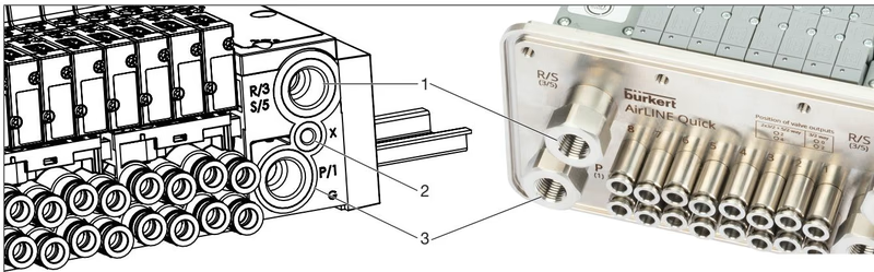
Primary air supply and ventilation lines enter through the connection units, while individual working ports connect underneath the pneumatic base modules.
| Connection / Fastener | Thread Size | Recommended Torque | Maximum Permissible Torque |
|---|---|---|---|
| Supply & exhaust connections (P, R/S) | G 1/4 | 4.0 to 7.0 Nm | 20.0 Nm |
| Auxiliary pilot connection (X) | M5 | 1.0 to 1.2 Nm | 3.0 Nm |
| Push-in fittings AirLINE Quick | M7 | 1.75 to 2.25 Nm | 4.0 Nm |
| Valve mounting screws (Type 6524/6525) | M2 | 0.25 to 0.30 Nm | 0.35 Nm |
| Valve block rail locking screws | M4 | approx. 1.8 Nm | 2.0 Nm |
Avoid Port Inversion
Ports 1 (P) and 3/5 (R/S) must never be interchanged. Connecting supply pressure to exhaust channels will damage pilot seats and cause uncontrolled valve movements.
When planning control cabinets with Bürkert Type 8647 and Siemens distributed I/O, distinct architectural guidelines apply:
| Planning Parameter | In Combination with ET 200SP | In Combination with ET 200SP HA |
|---|---|---|
| Hardware mounting rail | Standard rail TH 35 (EN 60715) | Siemens ET 200SP HA profile rail |
| Upstream power BaseUnit | Light-colored BaseUnit (BU...D) recommended | Light-colored BaseUnit (BU...D) mandatory |
| Extension to the right of valve block | Permissible (requires new BU...D feed) | Not permissible (server module must terminate) |
| Multiple valve blocks in one station | Yes (with additional power infeed) | No (maximum 1 valve block per station) |
| Total module limit on station | Up to 64 modules / connection blocks | Up to 56 modules / connection blocks |
| Integration software | STEP 7 Classic, TIA Portal, PCS 7 | PCS 7 (V9.0 SP2+ with HUP) |
Separate Load Power Supply
Due to the ±10% voltage tolerance requirement of solenoid pilot coils, install a light-colored Siemens BaseUnit (BU...D or BU...D/T) immediately to the left of Type 8647 to create an independent potential group isolated from noisy peripheral loads.
Type 8647 accommodates several safety-related shut-off architectures:
Safety Notice for HotSwap Operations
When removing a valve from a live HotSwap base module, residual compressed air exhausts briefly, depressurizing working line 2 (A) or 4 (B). Connected process actuators will move to their unpressurized rest positions. Secure actuators against motion and wear protective safety glasses before loosening valve retaining screws.
Only genuine Bürkert REV.2 spare valves and accessories should be fitted to article 20099403:
| Article No. | Designation | Description / Function |
|---|---|---|
| 20029918 | Type 6524 3/2-way NC | REV.2 single valve, FM20 flange, 2.5–10 bar, 24 V DC, manual override |
| 20029919 | Type 6524 3/2-way NO | REV.2 single valve, FM20 flange, 2.5–10 bar, 24 V DC, manual override |
| 20029920 | Type 6525 5/2-way | REV.2 single valve, FM20 flange, 2.5–10 bar, 24 V DC, manual override |
| 204710 | Type 6524 2×3/2-way NC | Double valve, FM20 flange, 2.5–10 bar, 24 V DC, manual override |
| 300817 | Type 6524 2×3/2-way NC | Double valve with auxiliary pilot air, 1–10 bar, 24 V DC |
| 661092 | Cover plate REV.2 | Covers unpopulated valve slots on 6524/6525 REV.2 pneumatic modules |
| 653670 | Electrical cover | Covers unused electrical sockets on PQ electronic modules |
| 20024336 | Valve seal set FM24 | Pack of 12 spare flange seals for Type 6524 3/2-way REV.2 valves |
| 20016305 | Valve seal set FM20 | Pack of 12 spare flange seals for Type 6524 2×3/2-way and 6525 REV.2 valves |
Mount the valve island horizontally or vertically inside a suitable control cabinet rated at least IP54.
Explore similar products in our catalog


