

PN16

BURKERT 20099566 Type 8652 AirLINE is an 8-slot valve island with Industrial Ethernet, AirLINE Quick aluminium plate, D10 and D6 brass push-in connections, 4 CF-C SIA valves, and 4 CF-L 5/3 valves.
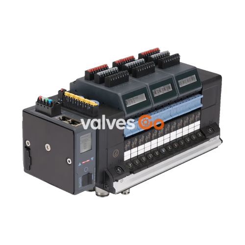
BURKERT 20099566 (Type 8652) AirLINE is an 8-slot pneumatic valve island developed for process automation architectures. The system integrates an LC display that shows diagnostics in both clear text and symbols to accelerate commissioning and plant status checks. Integrated check valves in the exhaust channels prevent unwanted actuator movement caused by backpressure peaks, while the pneumatic HotSwap mechanism on port 1 (P) permits valve replacement under full system operating pressure.
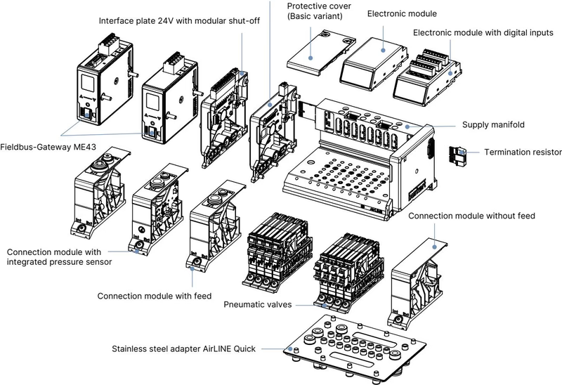
Preconfigured under article number 20099566, the assembly includes an anodised aluminium AirLINE Quick base plate, an ME43 Industrial Ethernet communication module with dual RJ45 ports, and 8 installed valve slices. Valve positions 1 through 4 are equipped with Type 6534 SIA safety-related shut-off valves, while positions 5 through 8 house 5/3-way closed center valves.

Article 20099566 is factory assembled with the following slot assignment and process port sizing:
| Slot Position | Valve Function | Circuit Type | Safety / Features | Working Port Size / Material |
|---|---|---|---|---|
| Position 1 | 2x 3/2-way NC | CF-C | SIA Safety shut-off | D6 mm push-in, Brass |
| Position 2 | 2x 3/2-way NC | CF-C | SIA Safety shut-off | D6 mm push-in, Brass |
| Position 3 | 2x 3/2-way NC | CF-C | SIA Safety shut-off | D6 mm push-in, Brass |
| Position 4 | 2x 3/2-way NC | CF-C | SIA Safety shut-off | D6 mm push-in, Brass |
| Position 5 | 5/3-way closed center | CF-L | Standard pilot valve | D6 mm push-in, Brass |
| Position 6 | 5/3-way closed center | CF-L | Standard pilot valve | D6 mm push-in, Brass |
| Position 7 | 5/3-way closed center | CF-L | Standard pilot valve | D6 mm push-in, Brass |
| Position 8 | 5/3-way closed center | CF-L | Standard pilot valve | D6 mm push-in, Brass |
All pneumatic supply connections (port 1) use D10 mm brass push-in fittings, with auxiliary pilot air fed internally.
| Specification Parameter | Value |
|---|---|
| Valve slice width | 11 mm per station |
| Number of valve slots | 8 slots (Type 8652 family supports up to 24 slots / 48 functions) |
| Body material | Polyamide (PA) |
| Seal materials | NBR and PUR |
| Operating medium | Lubricated or oil-free dry compressed air, neutral gases (5 µm filtration recommended) |
| Compressed air quality | ISO 8573-1:2010, Class 7.4.4 |
| Operating pressure range | -1.00 bar to 10.00 bar (vacuum to 10 bar) |
| Auxiliary pilot pressure | 3.00 bar to 10.00 bar |
| Nominal flow rate QNn (air) | 310 l/min (measured at +20 °C, 6 bar inlet pressure, 1 bar pressure drop) |
| Flow reduction with HotSwap | Approx. 3% |
| Operating voltage | 24 V DC (±10%), residual ripple 1 Vss |
| Nominal power per valve | 0.7 W nominal (drops to 0.175 W after internal power reduction) |
| Nominal current per valve | 29 mA (drops to 10 mA after internal power reduction) |
| Operating mode | 100% continuous duty (ED) |
| Switching time measurement | According to ISO 12238 (opening: 15–20 ms, closing: 15–25 ms depending on function) |
| Electric shock protection | Class III according to DIN EN 61140 / VDE 0140 |
| Degree of protection | IP20 bare; IP65 inside closed cabinet with AirLINE Quick plate |
| Ambient and medium temperature | -10 °C to +55 °C |
| Storage temperature | -20 °C to +60 °C |
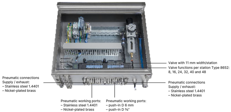
The AirLINE Quick adapter plate allows direct mounting of the valve terminal into the bottom or side wall of a control cabinet. This eliminates bulkhead tube feedthroughs and shortens pneumatic tubing runs.
| Component Feature | Specification |
|---|---|
| Adapter plate material | Anodised aluminium (1.4301 stainless steel optionally available) |
| Pneumatic push-in fittings | Nickel-plated brass (1.4401 stainless steel optionally available) |
| Supply and exhaust connections (1, 3, 5) | Push-in D10 mm (or 3/8") |
| Working ports (2, 4) | Push-in D6 mm (or 1/4") |
| Mounting location | Control cabinet floor cut-out or control cabinet side wall |
| Seal integrity | Maintains IP65 enclosure integrity when mounted in an approved control cabinet |
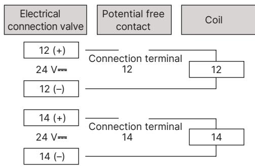
Type 8652 utilizes Type 6534 pilot solenoid valves. Positions 1 to 4 on article 20099566 incorporate the SIA (Safety-related shut-off) variant. The SIA valve features an independent two-wire external circuit interruption interface, allowing potential-free contact interlocks (mechanical switches or safety relays) to disconnect pilot valve power immediately.
| Valve Variant | Function | Normal Position | Manual Override | Safety Interlock (SIA) |
|---|---|---|---|---|
| 6534 SIA (Pos. 1–4) | 2x 3/2-way (CF-C) | Normally closed | None (for safety integrity) | Pluggable 2-pin coded terminal (0.5 A / 24 V DC) |
| 6534 Standard (Pos. 5–8) | 5/3-way (CF-L) | Middle position closed | Latching / spring return | Controlled via bus system |
Safety Circuit Delivery State
On delivery, SIA connection terminals are fitted with shorting jumpers to permit testing. Remove jumpers prior to wiring into the plant safety shutdown loop. SIA terminals accept conductor cross-sections between 0.14 mm² and 1.5 mm² (AWG 28–16).
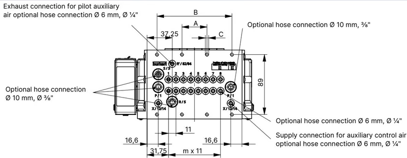
For 8-slot valve terminals, the mounting and interface dimensions comply with the following schedule:
| Variant | A (mm) | B (mm) | Mounting Holes C | Valve Stations m | Display Windows n |
|---|---|---|---|---|---|
| 4-fold | 66 | — | 4 x M5 | 3 | 1 |
| 8-fold (20099566) | 35 | 111 | 8 x M5 | 7 | 2 |
| 12-fold | 77 | 154 | 10 x M5 | 11 | 3 |
Standard DIN rail mounting according to EN 50022 (35 x 7.5 mm or 35 x 15 mm) is also supported when installed outside cabinet floor cutouts.
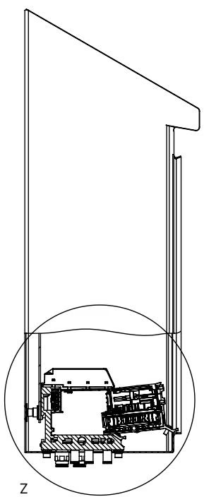
Cabinet Clearance for HotSwap
When installing the valve island inside a control cabinet, maintain the minimum clearance from the cabinet front door and lateral components shown in the manual. This spacing ensures sufficient room to actuate release clips and remove valve slices horizontally without depressurizing the main air rail.
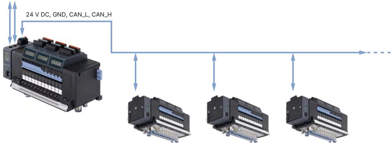
Power supply for electronics, display, and pneumatic pilot solenoids are separated to allow independent shutdown of valve power while keeping bus communications operational.
| Terminal Block | Pin | Wire Colour Code | Signal Assignment |
|---|---|---|---|
| 5-pin spring terminal (Logic & Display) | 1 | Red | +24 V DC (Logic) |
| 2 | White | CAN_H (büS interface) | |
| 3 | Green | Shielding | |
| 4 | Blue | CAN_L (büS interface) | |
| 5 | Black | 0 V DC (GND) | |
| 2-pin spring terminal (Pneumatics AUX) | 1 | Red | AUX +24 V DC (Valve coil power) |
| 2 | Black | 0 V DC (GND) |
Maximum conductor cross-section for both spring terminal strips is 1.5 mm².
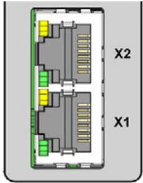
The ME43 communication module features two RJ45 ports (X1, X2) supporting line and star topologies for PROFINET IO, EtherNet/IP, Modbus TCP, EtherCAT, and CC-Link IE Field Basic:
| RJ45 Pin | Industrial Ethernet Signal |
|---|---|
| 1 | TX+ |
| 2 | TX- |
| 3 | RX+ |
| 4 | Not connected (N.C.) |
| 5 | Not connected (N.C.) |
| 6 | RX- |
| 7 | Not connected (N.C.) |
| 8 | Not connected (N.C.) |
Type 8652 valve islands hold certifications for Zone 2 gas and Zone 22 dust hazardous environments when housed inside appropriate enclosures.
| Authority / Standard | Classification Code | Certificate Reference |
|---|---|---|
| ATEX | II 3G Ex ec IIC Gc II 3D Ex tc IIIC Dc | BVS 20 ATEX E 031 U |
| IECEx | Ex ec IIC Gc Ex tc IIIC Dc | IECEx BVS 20.0024 U |
| cURus HazLoc | Class I, Zone 2, AEx ec IIC Gc / Ex ec IIC Gc U Class II, Zone 22, AEx tc IIIC Dc / Ex tc IIIC Dc U Class I, Div 2, Groups A, B, C, D Class II, III, Div 2, Groups F, G | E-File standards UL 61010-1, CAN/CSA-C22.2 |
| CCC Ex | China Compulsory Certification for explosion protection | GB/T 3836.2021 |
Hazardous Area Installation Constraints
| Description | Order Code |
|---|---|
| Replacement valve Type 6534 SIA (CF-C 2x 3/2-way NC, 24 V DC) | 338802 (Ref 336443) |
| Replacement valve Type 6534 standard (CF-L 5/3-way closed center, 24 V DC) | 301380 (Ref 296036) |
| Dummy valve plate (blanking plate for unpopulated slot) | 335779 (Ref 327614) |
| 5-pin spring-loaded power terminal (Logic / Display) | 920180 |
| 2-pin spring-loaded power terminal (Pneumatics AUX) | 920442 |
| ME43 Fieldbus Gateway module (Industrial Ethernet) | 301799 |
| AirLINE Quick 8-slot height adapter (without intermediate feed) | 754960 |
| AirLINE Quick 8-slot retaining plate for external cabinet mounting | 60005566 |
| AirLINE Quick 8-slot blanking plate | 754965 |
| Cabinet mounting screw kit M5x10 A2 DIN 6912 (10 pcs) | 308661 |
| USB büS interface set 1 (Type 8923) for Bürkert Communicator | 772426 |
Explore similar products in our catalog


