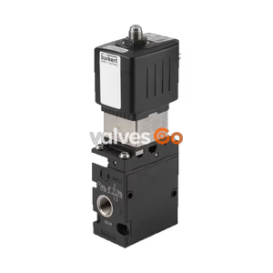
PN16

Burkert Type 8640 modular valve island (SKU 20106345) for pneumatics. Features 11 mm width per station, G 1/4 pressure port, multi-pole connection, and IP20 protection for complex control.
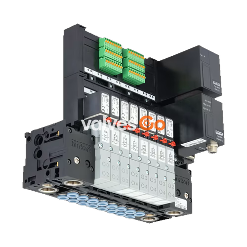
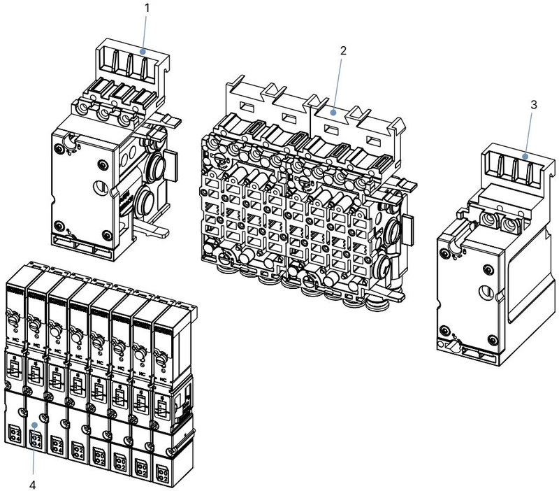
BURKERT Type 8640 modular valve island (SKU 20106345) is designed to solve diverse and complex control problems due to its systematic modular construction and combination of pneumatic and electrical interfaces. By putting together a row of pneumatic modules with different numbers of valves, 2 to 24 valve functionalities may be realized on one valve unit.
Bodies and connection modules are made of high-quality plastic (polyamide) and are easy to assemble by means of the built-in snap connectors. The 11 mm width per station variant supports a mixed valve population and features a multi-pole electrical connection, making it highly flexible for control cabinet installations.
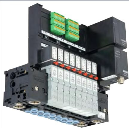
The following specifications apply to the 11 mm width per station configuration, utilizing pilot valves such as Type 0460, Type 6524, and Type 6525.
| Feature | Specification |
|---|---|
| Material (Body) | PA (polyamide), aluminium (Type 0460) |
| Material (Seal) | FKM, NBR and PUR |
| Width per station | 11 mm |
| Manual override | Standard |
| Number of valve slots | Max. 24 (Max. 12 for impulse and double valves with multipole connection) |
| Pressure range | Vac...10 bar |
| Operating voltage | 24 V DC (±10% tolerance) |
| Nominal power per valve | 0.8 W (Single valves); 2x0.8 W with power reduction (Impulse/double valves) |
| Degree of protection | IP20 (IP65 in closed control cabinets) |
| Operating medium | Oil-free or lubricated compressed dry air, neutral gases (5 μm filter recommended) |
| Ambient temperature | 0 °C...+ 55 °C (0 °C...+ 50 °C when using Type 0460) |
The electrical connectivity is achieved via multi-pole interfaces, allowing for streamlined wiring and integration.
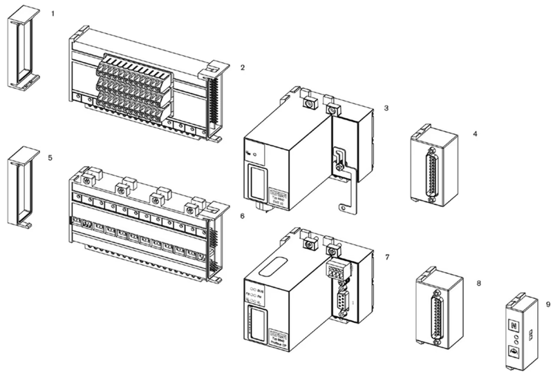
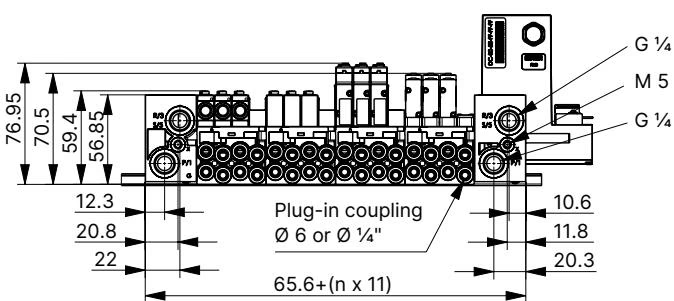
Dimensions for the 11 mm width per station pneumatics configuration (in mm, unless otherwise stated):
DANGER
Risk of injury due to high pressure and escaping medium. Switch off the pressure before working on the device or system. Vent or drain the pipes.
Risk of injury due to electric shock. Switch off voltage before working on the device or system. Secure against reactivation. Observe any applicable accident prevention and safety regulations for electrical devices.
WARNING
Risk of injury from quickly accelerating device parts and unconnected compressed air hoses flapping around. Before applying pressure to the valve, check all hose connections and fittings for tight, secure fit.
NOTE
Pilot pressure: For pneumatic control units, the pilot pressure depends on the pressure of the flow medium; it must be between 2 ... 10 bar (at least 70% of operating pressure).
Pressure difference: Ensure a pressure difference between port 1 and 3 of at least 2 bar. When temperatures are below 0 °C, operation is restricted to dried air.
To ensure optimal performance and prevent leakage with push-in connectors:
Explore similar products in our catalog