Type 2032

BURKERT 20113252 (Type 2933) is a manual 2/2-way diaphragm valve with forged 316L body, DN 40 ASME BPE clamp connection, PTFE/EPDM diaphragm, 0-10 bar operating pressure, and optical stroke indicator.
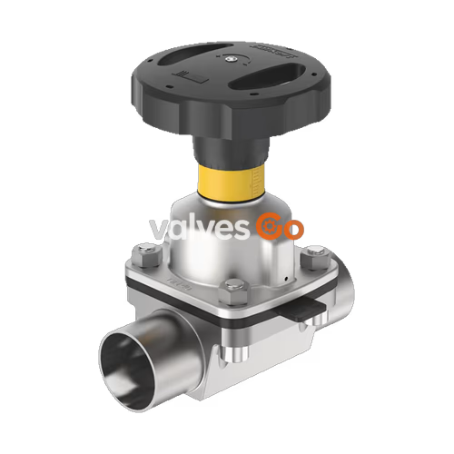
BURKERT 20113252 (Type 2933) is a manually operated 2/2-way diaphragm valve engineered for ultra-pure, sterile, aggressive, or abrasive fluid isolation. Built with a forged 316L / 1.4435 BN2 stainless steel body, this configuration integrates an ASME BPE DN 40 (1 1/2") clamp port, a PTFE/EPDM backed diaphragm (size 40), and an autoclavable polyphenylene sulphide (PPS) bonnet and handwheel actuator. The flow-optimised, zero-deadleg interior profile achieves a water Kv value of 37.5 m³/h (Cv 43.7 gal/min) while supporting bidirectional shut-off up to 10 bar.
Equipped with an integrated visual position indicator and an adjustable closing limiter, the manual actuator protects sealing faces against over-tightening. All product-wetted stainless steel surfaces feature an electropolished internal finish with Ra ≤ 0.38 µm, certified to ASME BPE SF4 and DIN HE4 standards. Complete traceability is documented through an enclosed EN 10204 3.1 inspection certificate, while the sealing system conforms to USP Class VI, FDA 21 CFR 177, and EC Regulation 1935/2004 requirements for pharmaceutical, biotechnology, and food processing systems.
| Technical Parameter | Specification / Measured Value |
|---|---|
| Article Number (Ident) | 20113252 |
| Valve Type / Concept | Type 2933 (Basic manual actuator) |
| Valve Function | 2/2-way shut-off valve |
| Nominal Port Diameter | DN 40 (NPS 1 1/2") |
| Port Connection Type | Sanitary Tri-Clamp |
| Process Connection Standard | ASME BPE / BS 4825-3 (tube 38.1 x 1.65 mm, clamp collar 50.5 mm) |
| Valve Body Material | Forged stainless steel 316L / 1.4435 BN2 (VS) |
| Diaphragm Material | PTFE with EPDM backing diaphragm (code EA) |
| Diaphragm Size | 40 |
| Actuator Bonnet Material | Polyphenylene sulphide (PPS) |
| Handwheel Material / Size | PPS / Size M (110 mm diameter) |
| Operating Pressure Range | 0 to 10 bar (PN 10 / Class 150) |
| Medium Temperature Range | -10 °C to +130 °C (steam sterilisation up to +140 °C for 60 min) |
| Ambient Temperature Range | -10 °C to +130 °C (short-term up to +150 °C; autoclavable) |
| Flow Capacity | Kv = 37.5 m³/h (Cv = 43.7 gal/min) |
| Internal Surface Finish | Ra ≤ 0.38 µm (NO17, ASME BPE SF4 / DIN HE4, electropolished) |
| Stroke Limitation | Adjustable single minimum-stroke limiter (closing limiter) |
| Stroke Scale / Positions | 30 indexed rotation positions per handwheel turn |
| Position Feedback Preparation | M5 x 0.5 threaded sensor holes (proximity switches optional) |
| Cleaning Capabilities | CIP (Clean-in-Place) and SIP (Sterilise-in-Place) compliant |
| Included Certification | EN 10204 3.1 inspection certificate, 2.1 diaphragm certificate |
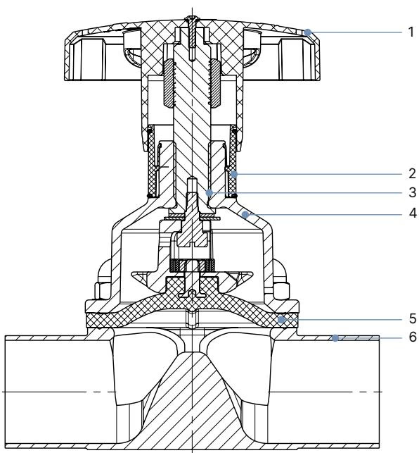
| Item No. | Element | Material Options / Current Configuration |
|---|---|---|
| 1 | Handwheel | Polyphenylene sulphide (PPS) [configured] or Stainless steel 1.4308 |
| 2 | Visual position indicator | Polyamide (PA), Stainless steel 1.4305 |
| 3 | Valve spindle | Stainless steel 1.4305 |
| 4 | Diaphragm bonnet | Polyphenylene sulphide (PPS) [configured] or Stainless steel 1.4308 |
| 5 | Diaphragm | PTFE/EPDM (EA) [configured], EPDM (AD), Adv. PTFE (EU), GYLON®/EPDM (ER) |
| 6 | Valve body | Forged 316L / 1.4435 BN2 (VS) [configured], cast (VG), tube (VP), plastic |
Diaphragm Material Performance
| Diaphragm Size | Handwheel Size | Handwheel ∅ B [mm] | Open Height H1 [mm] | Closed Height H2 [mm] | Slope per Rotation [mm] |
|---|---|---|---|---|---|
| 6 | T | 35 | 49 | 42 | 1.5 |
| 8 | T | 35 | 54 | 49 | 1.5 |
| 15 | S | 45 | 84 | 78 | 1.75 |
| 20 | S | 45 | 95 | 86 | 1.75 |
| 25 | S | 45 | 101 | 90 | 1.75 |
| 32 | M | 110 | 129 | 115 | 2.0 |
| 40 (20113252) | M | 110 | 134 | 116 | 2.0 |
| 50 | M | 110 | 149 | 125 | 2.0 |
| 65 | H | 240 / 272 | 182 | 152 | 4.0 |
| 80 | H | 240 / 272 | 205 | 163 | 4.0 |
| 100 | H | 240 / 272 | 207 | 161 | 4.0 |
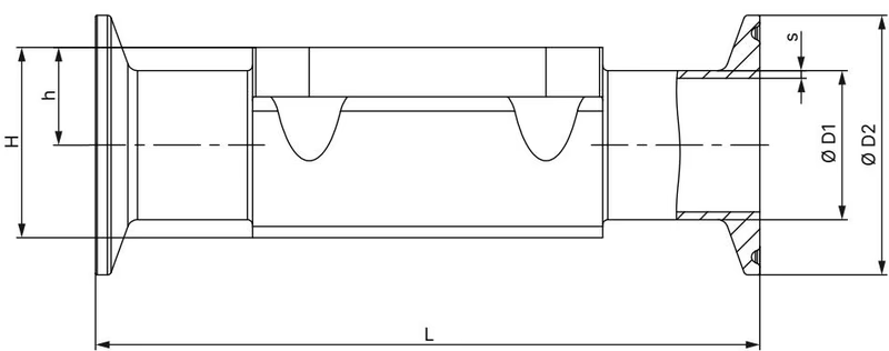
| Diaphragm Size | Port DN | Tube ∅ D1 [mm] | Wall s [mm] | Clamp ∅ D2 [mm] | Length L [mm] | h [mm] | H [mm] | Product Key | Variable Code |
|---|---|---|---|---|---|---|---|---|---|
| 6 | 1/4" | 6.35 | 0.89 | 25.0 | 63.5 | 8.5 | 18.0 | TG50 | — |
| 6 | 3/8" | 9.53 | 0.89 | 25.0 | 63.5 | 8.5 | 18.0 | TG01 | — |
| 6 | 1/2" | 12.7 | 1.65 | 25.0 | 63.5 | 8.5 | 18.0 | TG02 | — |
| 8 | 1/4" | 6.35 | 0.89 | 25.0 | 64.5 | 5.7 | 15.2 | TG50 | — |
| 8 | 3/8" | 9.53 | 0.89 | 25.0 | 89.0 | 5.7 | 15.2 | TG01 | AF34 |
| 8 | 1/2" | 12.7 | 1.65 | 25.0 | 64.0 / 89.0 | 9.3 | 18.8 | TG02 | — / AF34 |
| 15 | 1/2" | 12.7 | 1.65 | 25.0 | 89.0 / 108.0 | 8.15 | 19.85 | TG02 | — / AF34 |
| 15 | 3/4" | 19.05 | 1.65 | 25.0 | 89.0 | 12.05 | 23.75 | TG03 | — |
| 20 | 3/4" | 19.05 | 1.65 | 25.0 | 102.0 / 117.0 | 16.0 | 30.3 | TG03 | — / AF34 |
| 25 | 1" | 25.4 | 1.65 | 50.5 | 114.0 / 127.0 | 19.0 | 37.0 | TG04 | — / AF34 |
| 40 (20113252) | 1 1/2" | 38.1 | 1.65 | 50.5 | 140.0 / 159.0 | 27.6 | 52.4 | TG05 | — / AF34 |
| 50 | 2" | 50.8 | 1.65 | 64.0 | 159.0 / 190.0 | 35.5 | 68.3 | TG06 | — / AF34 |
| 65 | 2 1/2" | 63.5 | 1.65 | 77.5 | 249.0 | 43.0 | 83.5 | TG07 | — |
| 80 | 2 1/2" | 63.5 | 1.65 | 77.5 | 216.0 | 51.0 | 98.1 | TG07 | — |
| 80 | 3" | 76.2 | 1.65 | 91.0 | 222.0 | 51.0 | 98.1 | TG08 | — |
| 100 | 4" | 101.6 | 2.11 | 119.0 | 306.0 | 63.5 | 127.0 | TG09 | — |
| Diaphragm Size | Port DN [mm] | Port Size [in] | ISO 1127/11866 B [m³/h] | DIN 11850 2 [m³/h] | ASME BPE [m³/h] | BS 4825 [m³/h] | SMS 3008 [m³/h] |
|---|---|---|---|---|---|---|---|
| 6 | 8 | 1/4" | 2.2 | — | 0.7 | — | — |
| 8 | 10 | 3/8" | 1.5 | 1.5 | 1.6 | 1.4 | — |
| 15 | 15 | 1/2" | 6.5 | 6.5 | 3.1 | 3.7 | — |
| 20 | 20 | 3/4" | 12.5 | 12.4 | 8.4 | 8.9 | — |
| 25 | 25 | 1" | 18.0 | 20.0 | 15.5 | 15.5 | 16.0 |
| 40 | 32 | 1 1/4" | — | 34.0 | — | — | — |
| 40 (20113252) | 40 | 1 1/2" | 41.0 | 40.0 | 37.5 | 37.0 | 38.0 |
| 50 | 50 | 2" | 66.0 | 66.0 | 66.0 | 66.0 | 66.0 |
| 65 | 65 | 2 1/2" | 110.0 | — | 110.0 | — | — |
| 80 | 80 | 3" | 160.0 | 160.0 | 160.0 | — | — |
| 100 | 100 | 4" | 235.0 | 235.0 | 235.0 | — | — |
| Diaphragm Size | Max. Pressure [bar] | Static Tightness: EPDM [Nm] | Static Tightness: PTFE [Nm] | Dynamic Tightness: EPDM [Nm] | Dynamic Tightness: PTFE [Nm] |
|---|---|---|---|---|---|
| 6 / 8 | 10 | 0.6 | 1.1 | 0.9 | 1.2 |
| 15 | 10 | 0.8 | 1.7 | 1.5 | 2.5 |
| 20 | 10 | 0.9 | 3.0 | 2.0 | 4.5 |
| 25 | 10 | 1.2 | 3.5 | 3.6 | 5.0 |
| 32 | 10 | 2.5 | 4.0 | 8.0 | 15.0 |
| 40 (20113252) | 10 | 4.5 | 7.0 | 12.0 | 15.0 |
| 50 | 10 (PPS: 7) | 6.0 | 11.0 | 15.0 | 20.0 |
| 65 | 10 | 8.0 | 21.0 / 23.0 | 28.0 | 40.0 |
| 80 | 10 | 12.0 | 21.0 / 23.0 | 50.0 | 50.0 |
| 100 | 6 | 11.0 / 13.0 | 22.0 / 24.0 | 52.0 | 55.0 |
Sealing Definitions
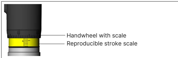
Turning the handwheel counterclockwise lifts the internal spindle, opening the fluid path and progressively revealing the yellow optical indicator. On actuator sizes 15 to 50, the indicator carries an indexed stroke scale. The handwheel circumference incorporates 30 position marks, allowing repeatable intermediate flow throttles.
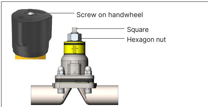
Type 2933 features an adjustable minimum stroke limiter housed inside the handwheel hub. This mechanism establishes a repeatable mechanical bottom stop, preventing diaphragm over-compression:
Stroke Limit Range Restriction
The minimum stroke limit is intended solely for diaphragm protection in the 0% to 25% opening stroke range. Do not engage the nut threads along the drive square profile.
The PPS bonnet includes two threaded bores for inductive proximity switch mounting. Switches detect the position of the internal compressor.
| Accessory Description | Thread / Standard | Article Number |
|---|---|---|
| Inductive proximity switch (initiator) M5 | M5 x 0.5 | 550412 |
| Inductive proximity switch (initiator) M5 ATEX | M5 x 0.5 (Ex-certified) | 904779 |
| 4-fold nylon locking mechanism with 3 mm bracket | Retrofit kit | 93719475 |
The valve mounts in any orientation, though installation with the actuator pointing vertically upward is preferred. When installed in sanitary process lines requiring complete drainability without media pooling, comply with the following criteria:
Pressure Relief Prior to Work
Depressurise pipelines and vent all lines completely before loosening body clamp connections or bonnet bolts. Hot media or trapped line pressure may cause burns and fluid spray.
| Diaphragm Size | Forged Body (VS) EPDM/FKM [Nm] | Forged Body (VS) PTFE/Adv. PTFE [Nm] | Tube Body (VP) EPDM/FKM [Nm] | Tube Body (VP) PTFE/Adv. PTFE [Nm] |
|---|---|---|---|---|
| 8 | 2.0 | 2.5 | 2.0 | 2.5 |
| 15 | 3.5 | 4.0 | 3.5 | 4.0 |
| 20 | 4.0 | 4.5 | 4.0 | 4.5 |
| 25 | 5.0 | 6.0 | 7.0 | 8.0 |
| 32 | 6.0 | 8.0 | 8.0 | 10.0 |
| 40 (20113252) | 8.0 | 10.0 | 12.0 | 15.0 |
| 50 | 12.0 | 15.0 | 15.0 | 20.0 |
| 65 | 20.0 | 30.0 | 20.0 | 30.0 |
| 80 | 30.0 | 40.0 | 30.0 | 40.0 |
| 100 | 40.0 | 40.0 | — | — |
Torque body screws crosswise in three progressive stages (approx. 1/3, 2/3, and 3/3 of final torque). A tolerance of +10% applies to all torque values.
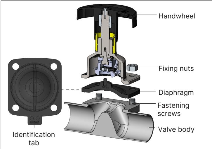
Under clean process operating conditions, the Type 2933 actuator is maintenance-free. Conduct routine visual inspections of the bonnet relief bore for fluid drops. Inspect the diaphragm after steam sterilisation or after a maximum of 100,000 operating cycles.
| Diaphragm Size | PTFE / Advanced PTFE (EA / EU) | EPDM / FKM / GYLON® (AD / FF / ER) |
|---|---|---|
| 8 | Buttoned connection | Buttoned connection |
| 15 to 20 | Bayonet catch | Bayonet catch |
| 25 to 100 (incl. Size 40) | Bayonet catch | Threaded connection |
| Diaphragm Type | Material Code | Fastening Method | Article Number |
|---|---|---|---|
| PTFE / EPDM (EA) | EPDM E04 / PTFE P05 | Bayonet catch | 20093073 |
| EPDM (AD) | EPDM E04 | Threaded connection | 688426 |
| FKM (FF) | FKM F01 | Threaded connection | 677689 |
| Advanced PTFE / EPDM (EU) | EPDM E04 / PTFE P06 | Bayonet catch | 20093084 |
| GYLON® / EPDM laminate (ER) | PTFE L08 | Threaded connection | 693180 |
When ordered with variable code PX51, Type 2933 complies with ATEX and IECEx standards for mechanical non-electrical equipment in Category 2G/2D zones:
| Temperature Class | Maximum Surface Temperature | Permissible Ambient Temperature | Maximum Medium Temperature |
|---|---|---|---|
| T4 | +135 °C | -40 °C to +100 °C | +125 °C |
| T3 | +200 °C | -40 °C to +130 °C | +185 °C |
| T2 | +300 °C | -40 °C to +130 °C | +285 °C |
Potential Electrostatic Charging Hazard
Explore similar products in our catalog